This thread has been locked.

If you have a related question, please click the "Ask a related question" button in the top right corner. The newly created question will be automatically linked to this question.

DLPC910: DMD image overlap (previous image stays on DMD when I display a new one)

Part Number: DLPC910
Other Parts Discussed in Thread: DLPC410

Hi,

In our application of FPGA driving DLPC910 and DMD module (DPL9000), We are facing an odd image-overlap on DMD. 

Please allow me to explain what kind of image-overlap I had in my design.

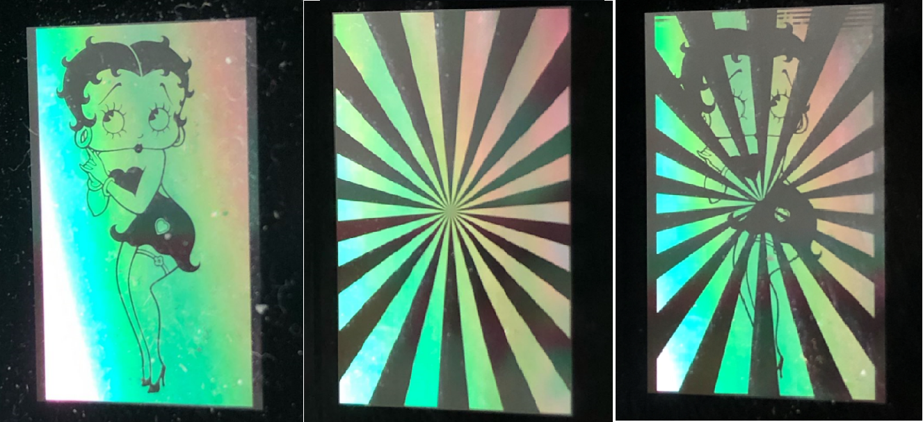
Let's say I firstly display a square on DMD and then display a circle, the normal result is that only a circle should be observed on DMD. 

But sometimes, I observed that square and circle are overlapped each other. I call this abnormal case image-overlap. 


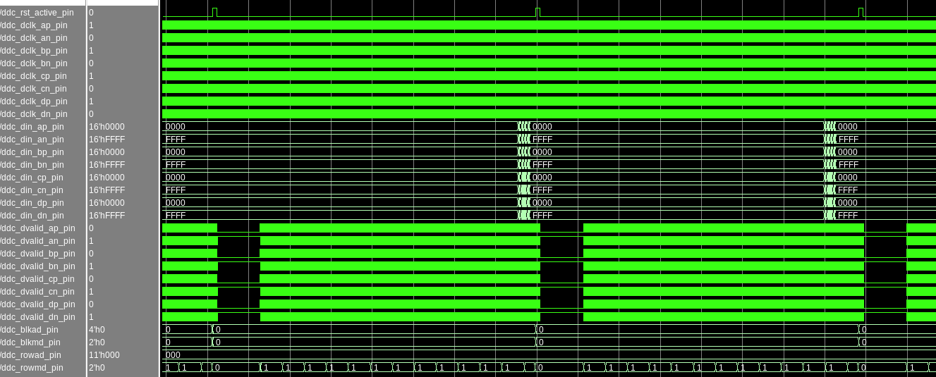
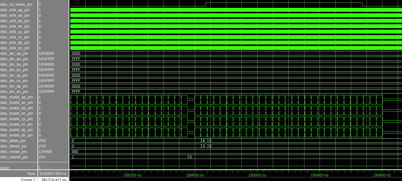
Below are the test results and observation I did 

1. because I need to keep refreshing DMD by using different image, I don't know when image-overlap is going to happen.

2. Once image-overlap happened, I have to keep refreshing the image I want to display until it can be displayed on DMD correctly, which means I don't know when image-overlap will go away. 

3. the first image after power cycle or DLPC reset is always good.

4. current walk-around is to do DLPC reset and LVDS training before I display image.  <-- apparently it is not the correct way to display an image

I am in trouble with this issue, could you guys please to help?

If you guys want me to provide more details for troubleshooting, please let me know. 

Thank you guys very much for any suggestion or information!!

Best!

  • Hello Zan,

    Before we can help can you confirm some things:

    Are you sending continuous data?  If so, are you following the advice in 

    DLPC910 / DLPR910A - Continuous Row Command Operation?

    Also, what reset mode are you using?  Single, Dual, or Quad block or Global?

    If you are using Global mode, are you allowing sufficient time for the reset to complete?

    Fizix

  • Hello Fizix,

    Thank you so much for your reply.

    we are using "Full DMD Global Load"

    Below waveform shows loading several images to DMD

    At the end of each "Full DMD Global Load" , We do DMD RST as shown below, I think it is global reset to reset all DMD blocks

    In below waveform, you can see the interval between two "Full DMD Global load".

    Again, really appreciate your help!

    Best,

  • Hello Fizix,

    BTW, DMD is set to 480-MHz Input Clock Rate.
  • Hello Fizix,

    Below is the picture of DMD showing the two images is ovelapped one over another.  Hope it can help you to understand my previous description on the current issue.

    Good focus image, Good lady image and Image-overlap

    We also observed that when image-overlap happens, there are some strip patterns on the top area of DMD (Not sure where it comes from..).

    Thank you very much for your help!

    Best,

  • Hello Zan,

    Thank you for the images.  These suggest that there may be an issue between the data timing and the global reset requests.  

    What FPGA are you using to input data to the DLPC910?. 

    Also can identify the corner of the images that are row 0, column 0?

    Fizix

  • Hello Fizix,

    We are using Xilinx Kintex Ultra FPGA to send data and control signals to DLPC910.

    About the row0, column0, please to see the red mark in the picture shown below.

    (my colleague told me, on the corner of DMD metal shell, the number means the row0 and col0.  and in current case, ns_flip = '0')

    Best,

    Zan

  • Hello Fizix,

    By implementing "Row Write Modes N/S Flip Flag = 0", our dmd data loading follows Table 3 of DMD spec "DLPC910_DataSheet_Preliminary_v0_2"
    Firstly, ROWMD=2'b11 , Clear row address pointer to 0 and write concurrent data into first row (that is, row ‘0’)
    Then, ROWMD=2'b01, Increment row address pointer and write the concurrent data into that row
    Totally 1600 rows are loaded.
    After the end of loading, we output BLKAD=4'b1000 and BLKMD=2'b11
    the Float-All is not implemented in curren design.


    I also suspect dmd reset. But it's hard to imagine how it could happen.
    Because, according to DMD spec, DLPC910 is going to assert RST_ACTIVE after receiving RESET ALL .
    and our FPGA design is going to detect the rising edge of RST_ACTIVE, keep outputing no-op row and waiting for the falling edge of RST_ACTIVE.

    Because we do receive high pulse of RST_ACTIVE after outputing RESET_ALL, which means DLPC910 must have received "some kind of" RESET CMD. Otherwise, DLPC910 won't output RST_ACTIVE.

    if DLPC910 receives One Block Reset or Four Blocks Reset instead of RESET ALL,
    what is going to display on DMD?

    if DLPC910 receives Float-All instead of RESET ALL, does it also output RST_ACTIVE?


    Thank you very much for your help!

    Best,
    Zan
  • Hello Zan,

    There is no logic in the DMD (or the DLPC910) to "or" the current binary pattern data state in the DMD CMOS memory with another binary pattern. It loads whatever data is received on the input during a row load and loads it to the specified row in the DMD. The DMD has no "or" function. I would really point you to looking at the actual data on a data input (to the DLPC910) line during this "incorrect" image.

    It is more likely that somehow the data has been "or'ed" in the Kintex FPGA before sending the data the the DLPC910 controller.


    Fizix

  • Fizix,

    Thank you very much for your reply. I will double check our FPGA design.

    Best,

    Zan

  • Zan,

    If you do not find anything, please let me know.  

    Fizix

  • Fizix,

    I found a clue about DLPC910 which may be the cause of my issue.

    By following below sequence,  I can repeat the image overlap anytime if I want to.

    display bitmap A on DMD   <- everything is OK

    wait about 1 min

    display bitmap B on DMD    <- here, I can observe overlap

    Looks like bitmap is related to waiting time between two bitmap images.

    And I am thinking this issue may related to the content in 8.5.3 of DLPC910 datasheet

    "Disabling the watchdog is not recommended unless the user
    ensures that a mirror clocking pulse to the entire DMD occurs within 10 seconds.

    During the time when the DLPC910 is in idle mode or is not operating, it is recommended to exercise the DMD mirrors by continuously loading
    an alternating all on all off patterns."

    if watchdog is enable but our FPGA doesn't "exercise the DMD mirrors by continuously loading an alternating all on all off patterns."  

    then what is going to happen in DLPC910 or DMD module after DLPC910 being in idle for long time ?


    Thank you very much!

    Best,

    Zan

  • Fizix,


    I found a clue about DLPC910 which may be the cause of my issue.

    By following below sequence, I can repeat the image overlap anytime if I want to.


    display bitmap A on DMD <- everything is OK

    wait about 1 min

    display bitmap B on DMD <- here, I can observe overlap


    Looks like bitmap is related to waiting time between two bitmap images.


    And I am thinking this issue may be related to the content in 8.5.3 of DLPC910 datasheet

    "Disabling the watchdog is not recommended unless the user
    ensures that a mirror clocking pulse to the entire DMD occurs within 10 seconds.

    During the time when the DLPC910 is in idle mode or is not operating, it is recommended to exercise the DMD mirrors by continuously loading
    an alternating all on all off patterns."

    if watchdog is enabled but our FPGA doesn't "exercise the DMD mirrors by continuously loading an alternating all on all off patterns."

    then what is going to happen in DLPC910 or DMD module after DLPC910 being in idle for long time ?


    Thank you very much!


    Best,


    Zan
  • Hello Zan,

    The watchdog timer simply issues a forced global reset, but again does not have any mechanism to "or" or "and" one binary pattern with another.
    I have worked with this architecture in the DLPC410 systems for many years and have not seen an occurrence of overlapped images in this way. The DLPC910 is based on the same architecture, with additional speed and with registers to aid in debugging.

    The overlapped image is too "clean". It appears to be a logic "and" (or an "or") between the two images. The controller simply passes the row data on to the DMD and controls the Mirror Clocking Pulse (Reset) timings to ensure that mirrors operate reliably.

    Fizix