This thread has been locked.

If you have a related question, please click the "Ask a related question" button in the top right corner. The newly created question will be automatically linked to this question.

DLP4710EVM-LC: Once again: how to go into 1440 Hz mode?

Part Number: DLP4710EVM-LC
Other Parts Discussed in Thread: DLP3010EVM-LC

Hello,

I'm re-posting this, because my question seems to have got lost.

I would like to operate the DLP4710EVM-LC in 1440 Hz 1-bit monochrome mode with external data over the HDMI input. The signal I'm sending is 1920 x 1080 at 60 Hz. Using the Light Control page of the GUI, in the External Patterns tab I set:

Illumination; G
Bit depth: 1
Patterns per frame: 24
Pre-exposure Dark Time: 210
Exposure Time: 447
Post-exposure Dark Time: 37

for a frame rate of 60.038 Hz.

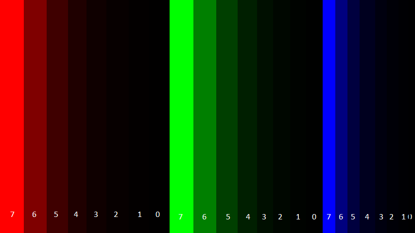
I'm trying to move a small square very rapidly across the screen, for example crossing the screen in 100 ms (144 frames). Each of the images I'm sending contains, in each of its 24 bit planes, the square in one of 24 successive positions. I've verified this pixel by pixel, bit by bit. The documentation says the first of 24 images to be displayed is PDATA 23 (most significant bit of red), etc. so the temporal order seems to be

R7 R6 R5 R4 R3 R2 R1 R0 G7 G6 G5 G4 G3 G2 G1 G0 B7 B6 B5 B4 B3 B2 B1 B0

When I code the images in this order, however, I don't seem to get the desired output. Individual images seem to contain vertical bands of non-homogeneous intensity (like dark-dark-medium-dark-light-dark-medium-...). Just in case, I also tried the orders

B0 B1 B2 B3 B4 B5 B6 B7 G0 G1 G2 G3 G4 G5 G6 G7 R0 R1 R2 R3 R4 R5 R6 R7
R0 R1 R2 R3 R4 R5 R6 R7 G0 G1 G2 G3 G4 G5 G6 G7 B0 B1 B2 B3 B4 B5 B6 B7
B7 B6 B5 B4 B3 B2 B1 B0 G7 G6 G5 G4 G3 G2 G1 G0 R7 R6 R5 R4 R3 R2 R1 R0

and I seem to get the same thing.

To answer's Azad's query from last week:

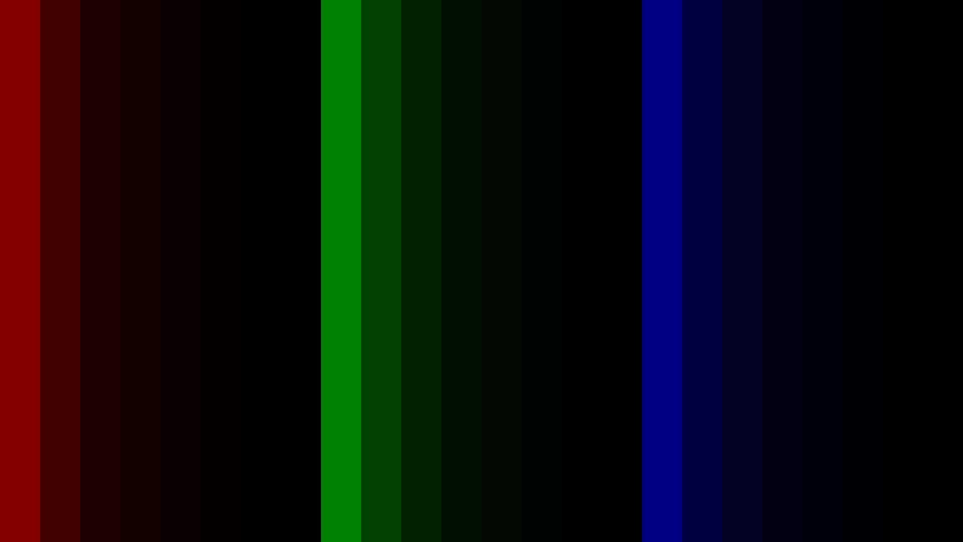
I've gotten rid of the artefacts for static images in 1440 Hz mode. It's the dynamic ones that are now giving me trouble. I'm attaching 6 images that, when shown in sequence, should result in a square moving from the left to the right of the screen over 144 frames, so 100 ms. The images look like they have bands, but actually each color bitplane contains the image of the square in a different position. So the bitplane of red bit 7 (most significant bit) contains the square in its leftmost position in each image, followed by the square slighly shifted to the right in red bit 6, and so on, in this sequence:

R7 R6 R5 R4 R3 R2 R1 R0 G7 G6 G5 G4 G3 G2 G1 G0 B7 B6 B5 B4 B3 B2 B1 B0

So when shown in succession, the sequence of the 6 attached images should produce a square moving from left to right on the screen over 100 ms. Given the speed and the "persistence of vision," this should be highly smeared, but the smear should be uniform, because each image should have the same luminance (the smear should actually taper off to the left). Instead, I see irregular, non-uniform vertical bars. As I said in my previous message, I tried all 4 possible sequences: RBG vs. GBR and bits 7-0 vs. 0-7, and all four seem to give the same artefacts (although some may be worse than others).

Do you have an explanation? Maybe the bitplanes aren't really shown in one of the 4 orders that I tried? Would you have an idea of what I need to do to get the desired output?

Mark

0310.bitplanes.zip

  • Hello Mark,

    Are you also able to upload one image of what the projection looks like?

    I noticed in your input images you uploaded you have some bands with multiple colors (i.e. red bits are in multiple location). You may instead want to try something like below.

    Thanks,

    Kyle

  • Thank you for your reply, Kyle. The overlaps are due to the fact that the square is wider than the step that it takes from frame to frame. I've rigorously checked that each of the 24 bitplanes corresponds to the square in one position, that moves from left to right across the 24 bitplanes, and across the 6 images. Is there some reason why that shouldn't work?
  • Kyle,

    I've now tried what you suggest. I'm enclosing the actual image file that I use (as opposed to what I was doing before, I'm not cycling through 6 images, I'm just displaying one image--as you suggested). This is what it looks like:

    The first stripe has RGB=(128,0,0), the second (64,0,0), ..., the 8th (0,128,0), etc. The actual image file is attached.

    I then switch to 1440 Hz 1-bit monochrome mode. As before, using the Light Control page of the GUI, in the External Patterns tab I set:

    Illumination; G
    Bit depth: 1
    Patterns per frame: 24
    Pre-exposure Dark Time: 210
    Exposure Time: 447
    Post-exposure Dark Time: 37

    for a frame rate of 60.038 Hz.

    The output I should get is bar moving from left to right 60 times per second. Since that motion is way too fast for human vision, I should get a uniform brightness throughout. That's not what I see. What I do see is a set of vertical bars of differing luminosities. I can't send you a photo because I only have a lousy smartphone camera, and the image it captures does not look like what I see. They look like this:

    • Divide the screen into 24 vertical bars (like the original image)
    • Consider the leftmost 8 bars
      • from left to right, the first bar is the brightest
      • the next 3 bars all have the same brightness, a bit lower that the previous one
      • the next 2 bars both have the same brightness, a bit lower the previous one
      • the next bar has a bit lower brightness
      • the next bar is the least bright
    • The other two thirds are about the same

    So do you have any idea about what's happening, and why I'm not getting the expected output?

    I had one idea myself: maybe my video card isn't sending the RGB values in that image file? Like it could be doing some color or luminance correction, altering the final colors it sends through the HDMI to the projector. This would add extra bits to the color planes, and could cause the kind of pattern I just described. But then: do you have any idea how I could send raw, precise, uncorrected RGB values to the projector through the HDMI output?

    Thank you,

    Mark Wexler

  • Oops, here is the image file

  • Hi Mark,

    Let us check this on our side and we'll get back to you within a couple of days.

    Regards
    Azad
  • Hi Mark,

    I'm able to confirm that as you mentioned, this is an issue with the video card on the computer. Some video cards might have an option to disable color correction features. If not, you can try varying the brightness and contrast of the HDMI video output (through the Display settings of your video card) to reduce this effect.

    Regards
    Azad
  • Hello Azad,

    Thank you for your reply. I'm a little bit disappointed, because I was hoping to use the 4710 EVM as a 1440 Hz projector driven by the HDMI signal.

    You wouldn't know of any video cards that could that have a way of disabling gamma and color correction, and just displaying the requested RGB bit-by-bit?

    Thank you,

    Mark

  • Hi Mark,

    We had a similar issue with the DLP3010EVM-LC's HDMI input.

    The HDMI decoder chip and the EVM's EDID are interpreted as a digital TV by the video card's driver and thus they may restrict the displayed range to (16-235) instead of (0-255).

    If you are using an nVidia card, you can check these settings in Nvidia Control Panel -> Display/Change Resolution -> Output dynamic range.

    Hope it helps

    Guillaume

  • Thank you, Guillaume, for your message. Are you saying that, with your Nvidia card on that setting, you get exact control of your RGB output bits? I mean that if you set a pixel to, for example (134,45,227), then you get an output of precisely (134,45,227), with no gamma or color correction of any kind? If so, I'd be VERY interested in knowing how you did that, because I'm told it's very complicated. Which video card do you use, and which OS? Did you have to change any other settings in the video driver or the operating system? Which software did you use to generate your images? Did you test your output in any way?

    Sorry for the multiple questions, but this information would be very, very useful for me.

    Mark Wexler
  • Hi Mark,

    To complete my previous, I tested my DLP3010EVM-LC on an Intel integrated GPU. In the graphics driver, the projector is detected as a Digital Television ITE6801. By default, the output range is also limited, the setting can be changed in Intel Graphics Settings -> General Settings -> Quantization Range.
    Unfortunately we do not have ATI/AMD cards at work but the driver should offer a similar setting.

    The machine I am using for my tests is a Dell XPS 8930 running Windows 10 Pro, and the GPU is a nVidia GTX 1060.
    I do most of my projector testing with a custom-designed test card, that has
    - R,G,B,W 0-255 gradients
    - R,G,B,W LSB to MSB squares (so for each color, the pixel values are 0,1,2,4,8,16,32,64,128,256)
    - fine horizontal and vertical detail
    I am projecting this test card using... the Windows desktop wallpaper (make sure it is using a lossless image format and that it is not recompressing the image using JPEG)

    The easiest way to test that the output is "pixel-exact" is to use the Light Control modes of the projector. For instance, using the 1-bit, 1-frame external pattern sequence mode, you should see the alternating LSB's of the blue and white gradients. If the display settings are left to the driver's default (except for the quantization/output range that should be set to full), the displayed pattern should be equidistant lines from end to end of the gradient.

    Additionally, by default the graphics card should not apply any gamma curve (it may if asked explicitly by the display's EDID) ; the gamma curve is applied by the display itself. On the DLP3010EVM-LC, the standard video modes use a degamma processing step, which is bypassed in Light Control modes.

    Best regards,
    Guillaume

  • I tried Guillaume's suggestion: using an Intel HD 620 graphics card on a Lenovo X1 Yoga (2nd gen.) laptop, I set the maximum range to full, and the 1440 Hz mode works! I'll now try Nvidia and AMD cards.

    I also realized that the temporal order of the bitplanes is the opposite of what the TI people had told me. The correct temporal order is:

    B-lsb B-msb G-lsb ... G-msb R-lsb ... R-msb

    Thank you very much, Guillaume, for your help.

    Mark

  • Hello Guillaume,

    While your suggestion of increasing the dynamic range to 0-255 works on a laptop with an Intel HD 620 graphics card, it doesn't work on another system, a desktop: Window 7 Pro SP1 with Nvidia Quadro K4200, with the DVI output connected up to the HDMI input of the projector. In the Nvidia parameters, in Video/Video parameters/Colors/Advanced (approximate names -- translated from French!), I put dynamic range to 0-255. It doesn't work: I use a test pattern like yours, based on powers of 2:

    (1,0,0)
    (2,0,0)
    (4,0,0)
    ...
    (128,0,0)
    (0,1,0)
    (0,2,0)
    ...

    This should yield a uniform color if there aren't any color or gamma corrections, right? I do not get a uniform color (as I do on my laptop with the Intel card). Do you have any idea of what else I can try on this system?

    Thank you,

    Mark

  • Hi Mark,

    Did you also change the dynamic range under the Change Resolution (Affichage/Changer la résolution) page ?

    AFAIK the settings under "Video" are only used when playing video content, which is not the case here.

    Also, my suggestion about using the Windows desktop to display the test slides does not apply (at least) on Windows 7. I was unable to achieve an uniform projection with the test slides given earlier in this thread, but it worked using the integrated image viewer.

    Best regards,

    Guillaume