A related question is a question created from another question. When the related question is created, it will be automatically linked to the original question.
If you have a related question, please click the "Ask a related question" button in the top right corner. The newly created question will be automatically linked to this question.
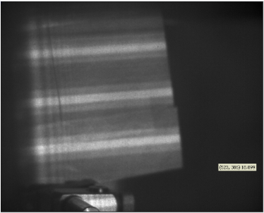
We were trying to use DMD chip to generate specific patterns, powered by laser sources. The DMD generates abnormal scattering stripes additional to the desired patterns. The scattering-like patterns are superimposed onto the desired patterns.
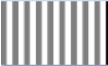
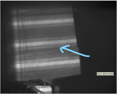
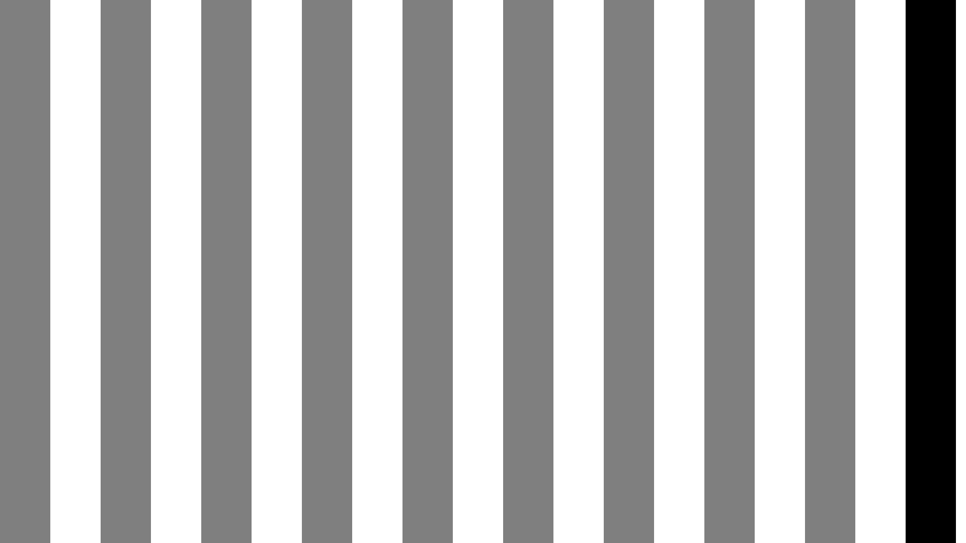
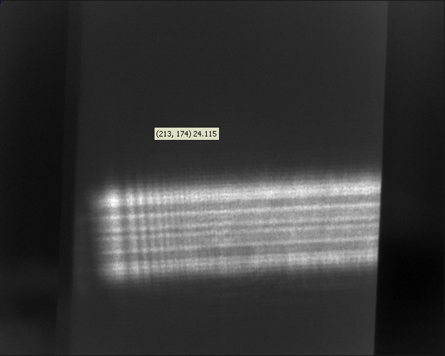
The upper image is the pattern generated and the lower image is the projection through a projector lens. The scattering-like patterns are marked in this image.
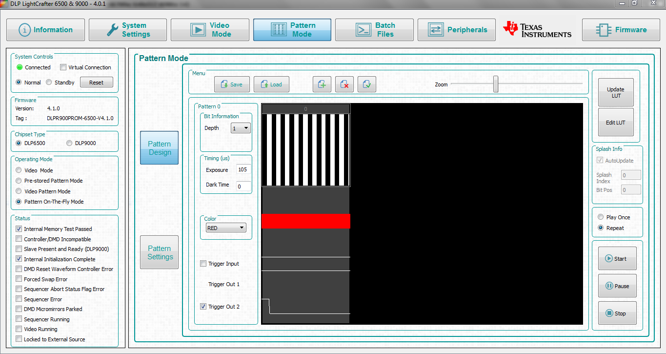
Please show the GUI setup information/screens and attach a file with at least the image file you are loading to the DMD. Without more information it will be difficult to assist you well.
Also can you tell me about your camera capture parameters?
I notice in your settings you have it set to 1 bit over 105 µs. Please change it to 8 bit (it will adjust the exposure to 4046 µs). I assume from the image you are attempting to to display gray stripes with one black stripe. What you are displaying is black stripes (since the gray is below the threshold value). I do not completely understand the picture though.
It would help to know how you are triggering (or if you are triggering) the camera to capture the image. You can use the Trigger Out 2 for that if needed.
Also in the picture can you tell me what it is being projected on? Is this a flat surface and is it uniform in color?
Well the problem is not about the color actually. I also used only black and white image and this is what I have after the dmd. The projected surface is a flat surface and it is white background with a checkerboard on it. It will look just the same with a white paper. I would like to know what is the cause of these fade stripes beside the pattern I want and how to solve this problem.
The wavelength is 980nm which is NIR. I can't see this directly with my eyes but it looks the same as the picture with an IR card. I use laser beam and it is collimated and expanded before it reach the DMD. Then after the reflection of the DMD it went through a concave lens for further expanding.
It is clear to me that you are getting edge diffraction from the stripe(s) and in the single stripe image it looks like slit diffraction and in the multi-stripe images it looks like orders from the multiple slits.
Currently we are trying to average out the edge diffraction by breaking the pattern into smaller parts and using minimum exposure time to display them. I have one question about the DMD setting. How does the "color" tab in the gui work? Does it change DMD's reaction to different colors?
The color tab in the DMD is only for Solid State Illumination (SSI) control. The DMD is reflective so, there is nothing that can change it's reaction to different colors of light.
However, the edge diffraction will change with wavelength according to wave mechanics.
I would take the single slit pattern you saw, and do a Fourier transform and put that pattern on the DMD to see if you can get a better image. However, If you are sending only binary patterns it may be challenging since your pattern will only have 0 or 1 for phase.