This thread has been locked.

If you have a related question, please click the "Ask a related question" button in the top right corner. The newly created question will be automatically linked to this question.

DLP3010EVM-LC: DLP3010EVM-LC: Trigger input does not work

Part Number: DLP3010EVM-LC
Other Parts Discussed in Thread: DLPC3478

I have a question about trigger input in DLP3010EVM-LC internal pattern streaming mode.

A external trigger signal was input to pin 5 of J4 on the light control display board under the following conditions, but no pattern was displayed.

What are the possible causes and solutions?

The settings on the hardware are as follows:

- connect pin 2 and 3 of J11 on main board

- connect pin 2 and 3 of J3 on light control display board

- for J4, use pin 5 as trigger in and pin 1 for ground

- Projector ON/OFF switch(SW1) is ON

The settings on the GUI tool are as follows:

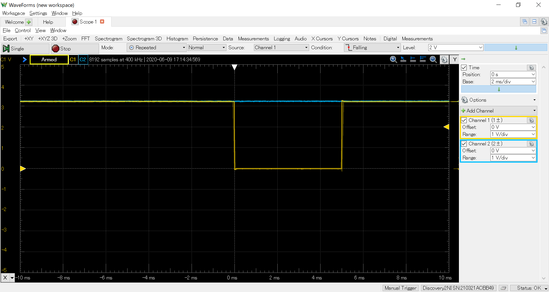
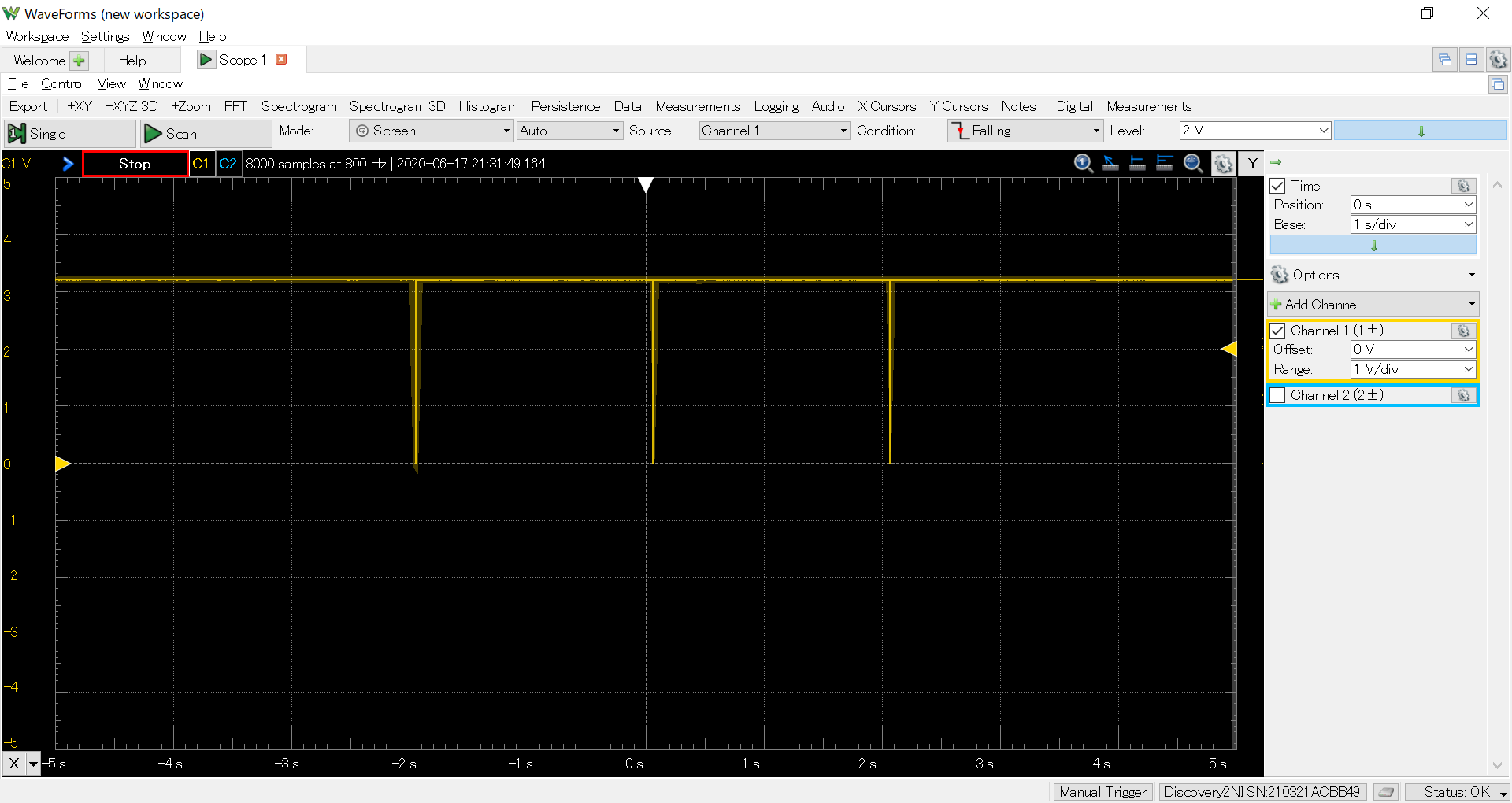
The input trigger signal (pin 5 of J4) and the pattern ready signal (pin 3 of J4) measured with the oscilloscope are as follows.

At this time, the ground is taken from pin1 of J4.

I am worried that the pattern ready signal is fixed at the high level voltage (The pattern ready signal is set to the active high).

- Channel 1 is the input trigger signal

- Channel 2 is the pattern ready signal 

There are similar questions below, but it seems they haven't been solved yet.

e2e.ti.com/.../3351933

Regards,

Yuta

  • Hi Yuta,

    Welcome to TI E2E forums! Thanks for the detailed problem description.

    Can you try out a couple of tests  -

    Are you able to display the patterns with exact same settings in the free running mode instead of the trigger_in mode. If yes, can you capture a screenshot of the pattern ready and trigger out 1 signal. 

    Also, are you ensuring that the period of trigger_in signal is greater than the summation of the given pre-exposure, exposure and post exposure time?

    Thanks and regards,

    Mayank

  • Mayank,

    Thank you for your reply.

    >Are you able to display the patterns with exact same settings in the free running mode instead of the trigger_in mode. If yes, can you capture a screenshot of the pattern ready and trigger out 1 signal.

    I have tried your suggested test.

    As a result, the pattern could be displayed normally in the free running mode with the trigger input set to disable.

    The settings on the hardware are the same as last time.

    The settings on the GUI tool are as follows:

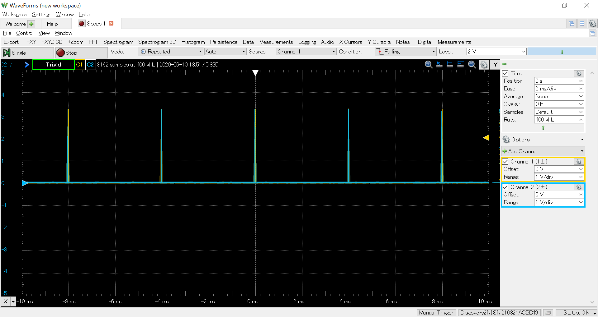
    The captured screenshots of the output trigger 1 signal(pin 7 of J4) and the pattern ready signal(pin 3 of J4) are as follows.

    At this time, the ground is taken from pin1 of J4.

    - Channel 1 is the output trigger 1 signal

    - Channel 2 is the pattern ready signal

    Also, an AC adapter with the following specifications is connected to the projector.

    - DC 19V output

    - Maximum output current 3.5A

    >Also, are you ensuring that the period of trigger_in signal is greater than the summation of the given pre-exposure, exposure and post exposure time?

    Yes.

    The trigger input cycle is at least 5 ms or more.

    On the other hand, the summation of the given pre-exposure, exposure and post exposure time specified by the GUI tool is 1.310 ms.

    Regards,

    Yuta

  • Yuta,

    I will try to reproduce the issue at my end and will let you know my findings soon.

    Regards,

    Mayank

  • Yuta,

    I tried reproducing the issue and i was able to display patterns using trigger in.

    Can you check whether you are able to display multiple patterns using input triggers of 1.8v level instead of 3.3v (For 1.8-V signal level : Connect pin 1 and pin 2 of J11)

    Thanks and regards,

    Mayank

  • Mayank,

    Thank you for confirmation.

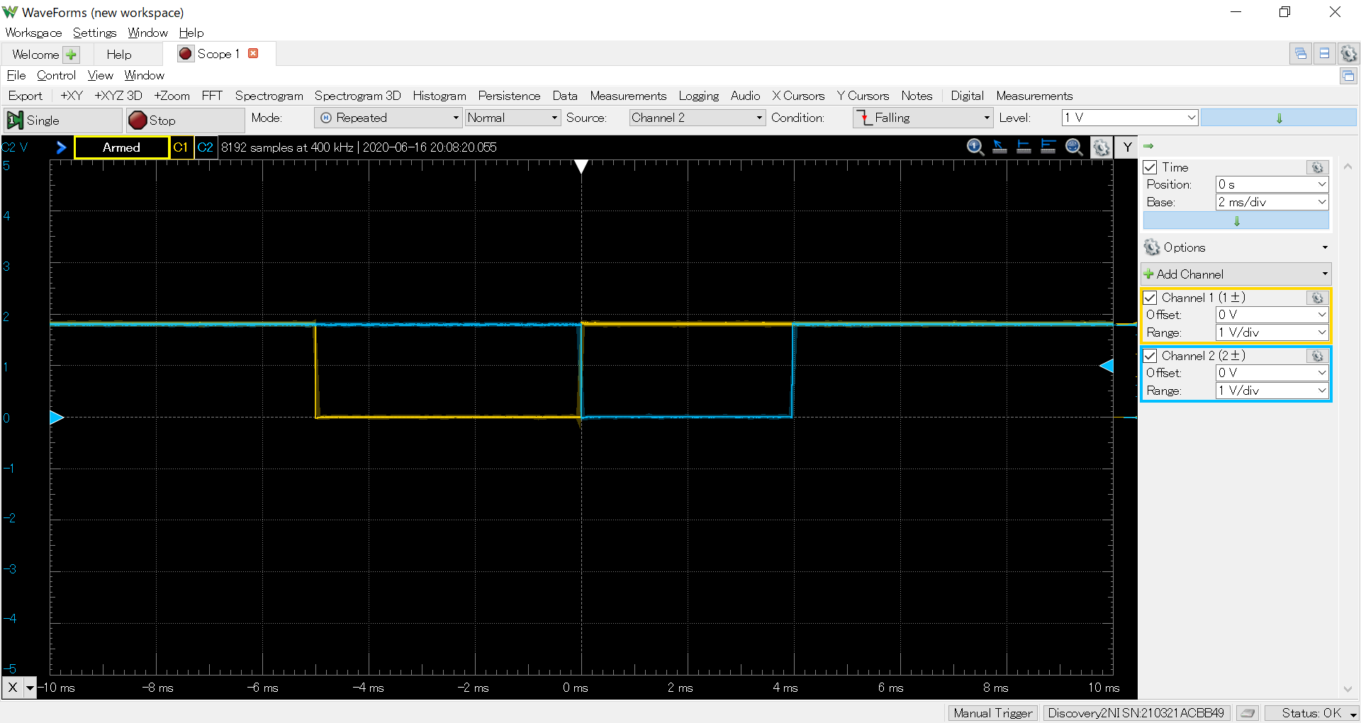
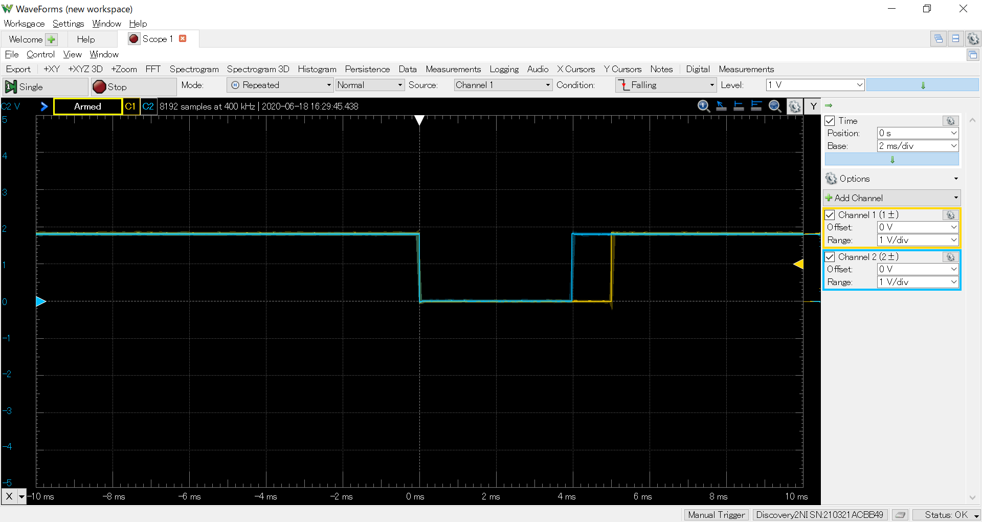
    According to your answer, I set the voltage level of the trigger input/output to 1.8V and checked the operation.

    Other settings are the same as for 3.3V.

    As a result, it was confirmed that the patterns could be output in synchronization with the trigger input.

    However, why doesn't it work at 3.3V?

    Could you tell me the possible causes?

    Regards,

    Yuta

    - Channel 1 is the input trigger signal

    - Channel 2 is the pattern ready signal 

  • Yuta San,

    Thanks for the feedback. 

    I will need some time to figure out why trigger in mode is not working for you with 3.3V signal levels. 

    Could you check whether the 3.3V signal levels are stable and within the specs.

    Thanks and regards,

    Mayank

  • Mayank,

    Thank you for your reply.

    I think the stability of the 3.3V signal is fine.

    The input trigger signal (pin 5 of J4) measured with the oscilloscope is as follows.

    At this time, the ground is taken from pin1 of J4.

    Also,the PWR_TP_SEN (pin 8 of J4) measured with the oscilloscope is as follows.

    At this time, the ground is taken from pin1 of J4.

    Does the DLP3478 firmware clearly distinguish between 1.8V and 3.3V trigger inputs?

    Regards,

    Yuta

  • Mayank,

    I have confirmed that the trigger input may not be detected even in the case of 1.8V.

    However, the probability of this phenomenon occurring is random.

    The reproduction procedure is as follows.

    (1)Set to 1.8V operation (connect PIN1 and PIN2 of J11).

    (2)Turn ON the ON/OFF switch on the main board.

    (3)Start the GUI tool and execute "Run Continuously" with the following settings.

    (4)Confirm that the pattern is projected and the Pattern Ready signal changes to Low level in synchronization with the input trigger signal.

    *The pattern may not be projected normally at this point

    *Although the pattern is projected, the Pattern Ready signal may not change to Low level (Pattern Ready signal is set to Enable).

    (5)Execute "Stop" to stop the projector operation.

    (6)Turn OFF the ON/OFF switch on the main board.

    (7)Turn ON the ON/OFF switch on the main board.

    (8)Click the "Get" button from the "Information" menu of the GUI tool and wait until the "Communication Error" is unchecked.

    (9)Execute "Run Continuously" with the same settings as last time.

    (10)When strobing the input trigger signal, the pattern may not be projected.

    By repeating (5)-(10) several times, you can see that the pattern may or may not be projected.

    I feel that the pattern is projected normally with a probability of 10% or less.

    If the pattern is not projected once, the same phenomenon tends to continue many times when repeating (5)-(10) (even if the pattern is projected once).

    In addition, the pattern may be projected but the Pattern Ready signal may not change to Low level (the Pattern Ready signal is set to Enable).

    From the above, I think there is a problem with one of the following.

    -GUI tools

    -DLPC3478 firmware

    -I2C communication

    Regards,
    Yuta

  • Mayank,

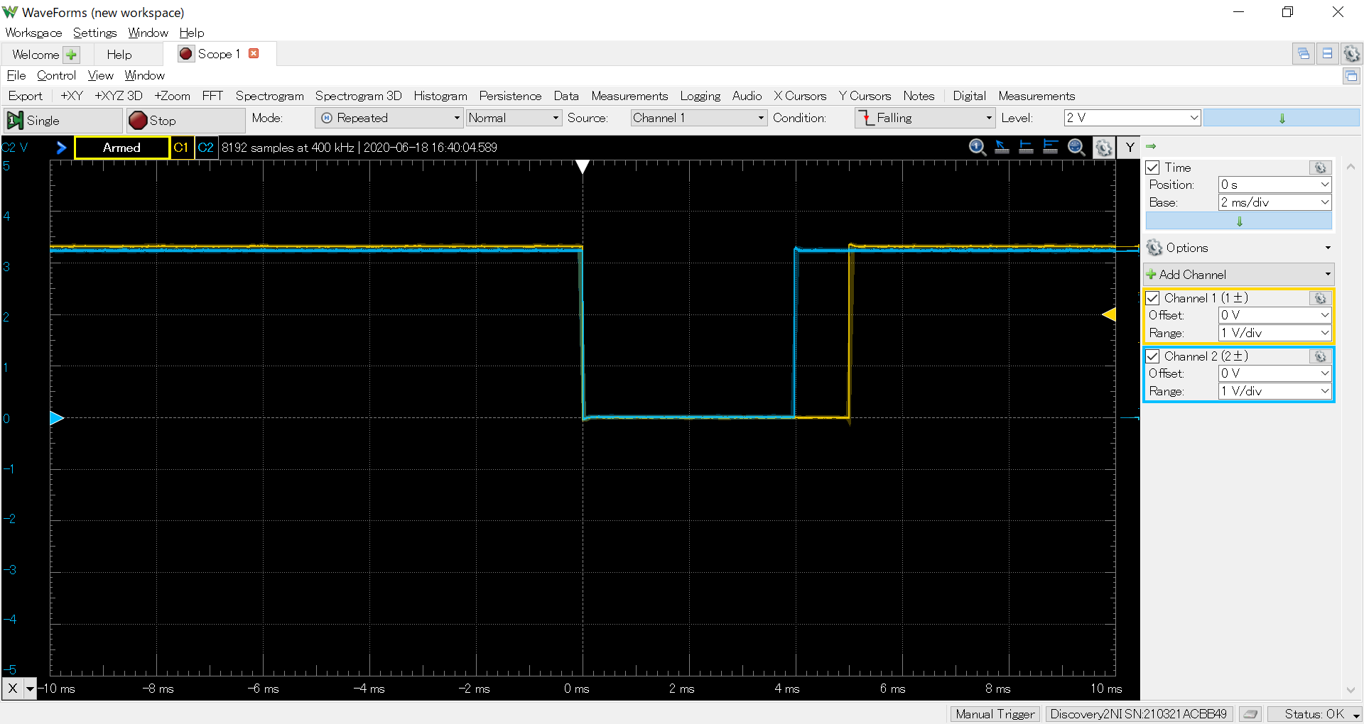
    I got another projector of the same product type and tried the operation of the trigger input in the same way.

    The DLPC3478 firmware versions are the same.

    As a result, both 3.3V and 1.8V could be projected normally in synchronization with the input trigger signal.

    The settings on the GUI tool are as follows:

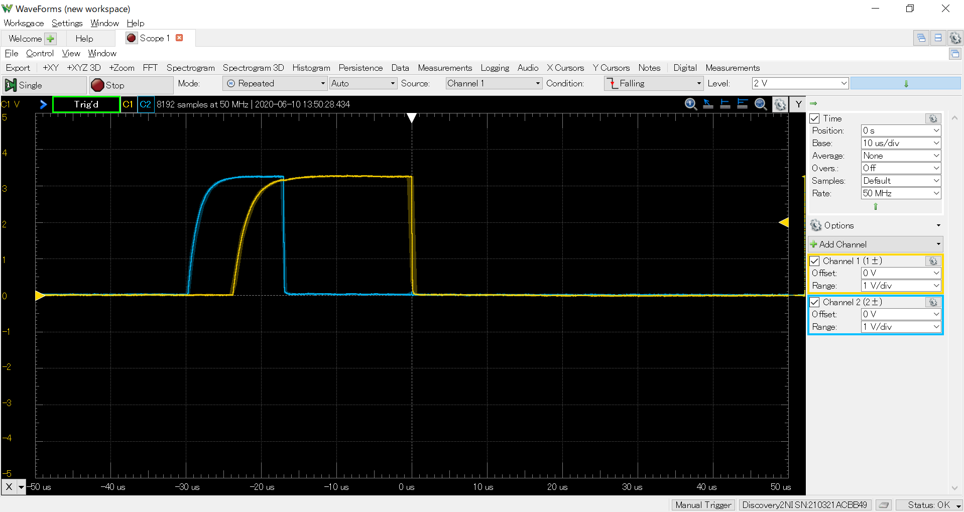
    The captured images of the input trigger signal (pin 5 of J4) and the pattern ready signal (pin 3 of J4) for 3.3V operation are as follows.

    At this time, the ground is taken from pin1 of J4.

    - Channel 1 is the input trigger signal

    - Channel 2 is the pattern ready signal

    The following is for 1.8V operation.

    From the above, in addition to the possibilities I presented last time, I thought there are the following possibilities.

    -My projector is broken

    -Operations vary depending on the projector product

    Regards,

    Yuta
  • Hi Yuta,

    Thanks for the update. 

    I am suspecting some hardware issue in your non-working projector. I rule out option 2 - as the operating behavior shouldn't vary across different EVMs.

    In order to debug the hardware issue, kindly refer to the EVM schematic ( https://www.ti.com/tool/TIDA-080003 )  in order to see the signal flow and check where it might be breaking.

    Regards,

    Mayank

  • Mayank,

    Thank you for your reply.

    If the EVM's behavior shouldn't vary across different EVMs, why is the following description in the manual?

    https://www.ti.com/lit/ug/dlpu070b/dlpu070b.pdf?ts=1592482525885&ref_url=https%253A%252F%252Fwww.ti.com%252Ftool%252FTIDA-080003

    page 8

    From this description, it can be read that the detection accuracy of the input trigger differs depending on the EVM.

    That's why I'm concerned about variability across different EVMs.

    In addition, the questioner below also doesn't have input triggers working as expected as I do.

    https://e2e.ti.com/support/dlp/f/94/p/905393/3351933?tisearch=e2e-sitesearch&keymatch=DLP3010EVM-LC%20trigger%20in#3351933

    What I expect from you is not to prove the quality of the product.

    What I expect from you is to suggest a possible solution to my current problem.

    Regards,
    Yuta
  • Yuta San,

    Apologies that I missed out on the note mentioned in the EVM manual.

    Can you please check and see whether the suggestions mentioned in the Note fixes the issue or not.

    Thanks and regards,

    Mayank