Other Parts Discussed in Thread: DLP4710
Hello TI Experts,
I have got a question about the DLP4710EVM-LC from our customer.
Would you please answer the question?
[Question]
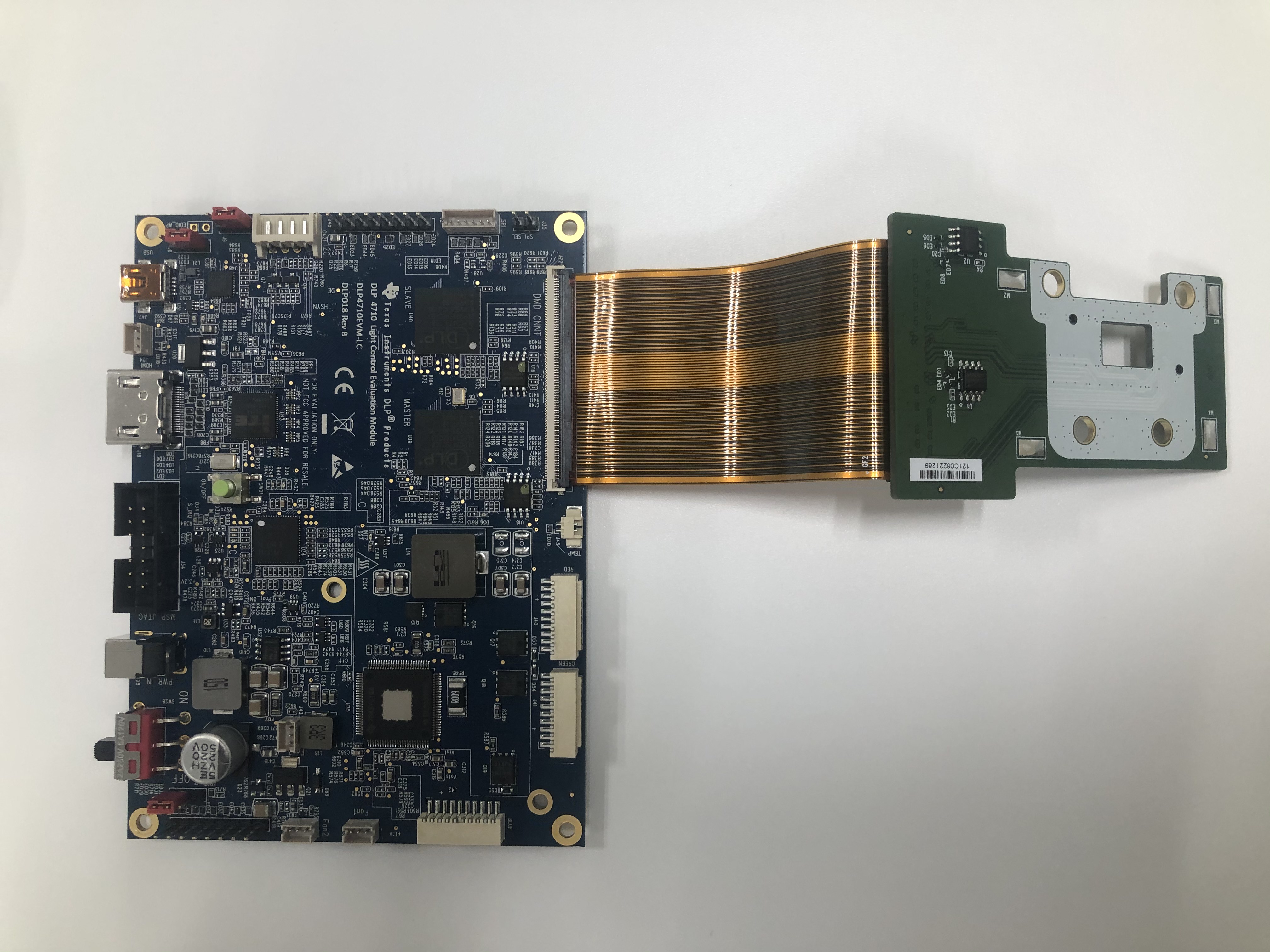
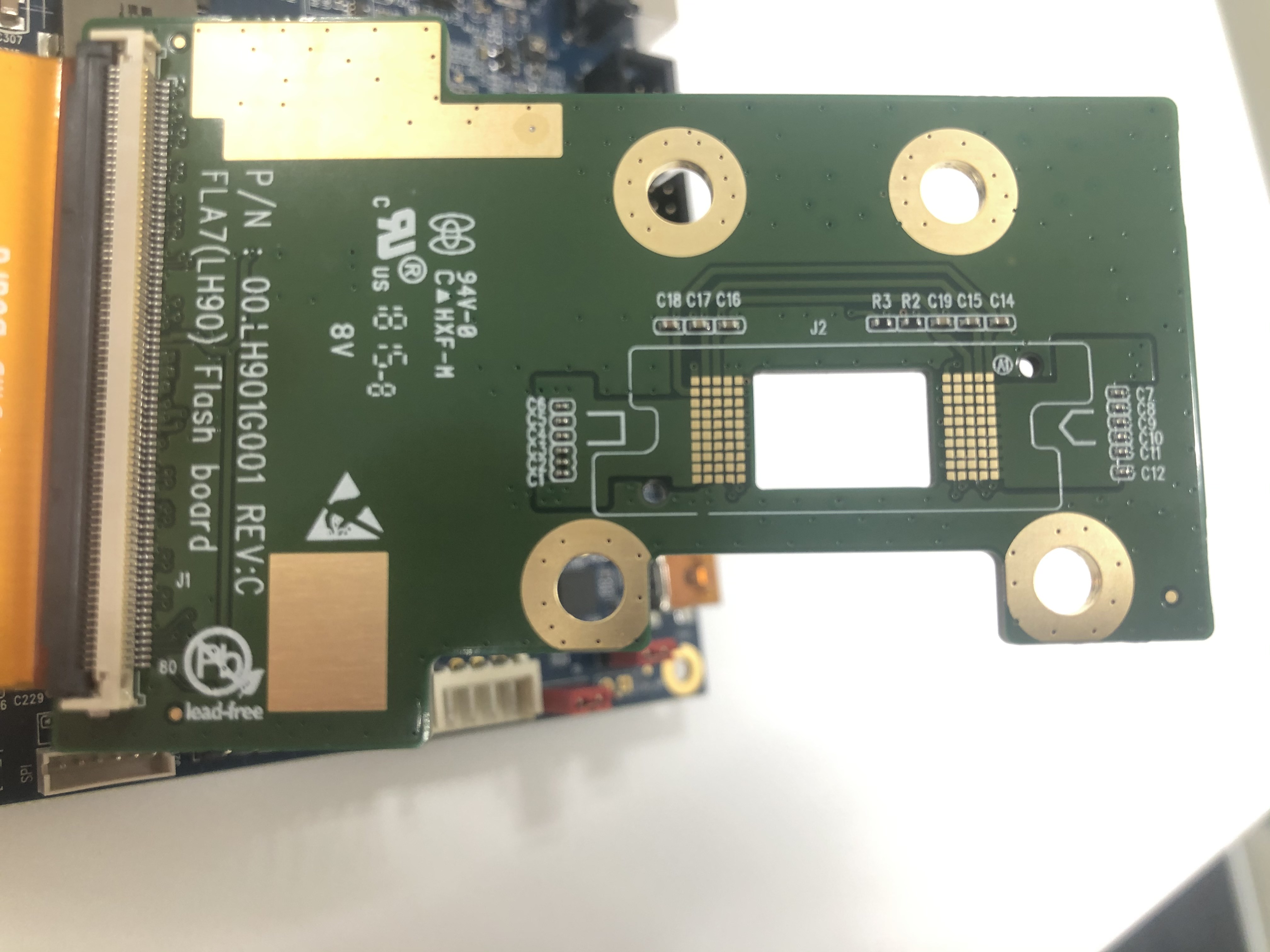
They recently bought and received the DLP4710EVM-LC. As they check the optical module inside of the evaluation kit, it looks the SPI Flash devices are mounted on both the optical module board and the controller PCB board like attached pictures. Would you please tell us which side of SPI flash devices are enabled? In the past, I asked the similar question with another thread below. At that time, the SPI flash devices should be used on the controller board. So, it would be helpful if you can tell us which flashes are enabled and how they can switch to use these devices.
I also would like to know about the capacitors, resistors and diodes on the optical module board. Would you please tell us what is the purpose of these discrete devices? It looks much more capacitors are mounted than the reference description on the DLP4710 datasheet. So, we would like to make sure the recommended capacitor values on the optical module side.
Thank you very much for your comment.
Nobu Arai