This thread has been locked.

If you have a related question, please click the "Ask a related question" button in the top right corner. The newly created question will be automatically linked to this question.

DLP4710: POM problem

Part Number: DLP4710
Other Parts Discussed in Thread: DLPC3439, , DLPC3479,

Hi,

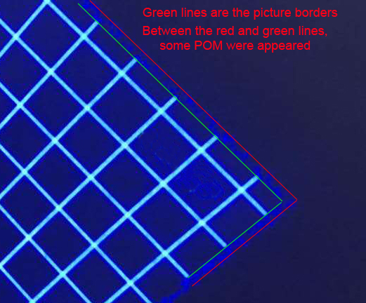
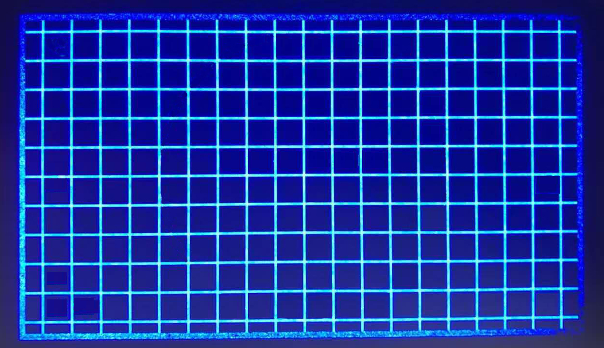
I have a DLP projector,recently when I project a black picture ,I can see a boder around the project area,I think there are something wrong with the POM mirrors,my questions are :

1.How to deal with it and how to prevent this problem?

2.It means that the DMD chip is going to die?

Beats regards,

YuanJian

  • Hi Yuan,

    Welcome to TI's E2E forum. Can you please provide more information so that we may help you better - Please attach an image showing the issue. 

    Thank you,

    Christopher Smith

  • Hi Christopher,

    Thanks for your quick response.

    I taked a picture ,it shows the corner of the project area(the picture resolution is 1920*1080),the green lines are the borders of the picture,but you can see other lines outside the picture's border.So I think there is something wrong with POM .

    Best regards,

    YuanJian

  • Hi YuanJian, 

    I have a few more questions that will help us to investigate:

    1. Are you using the DLP4710 EVM or is this a custom build?

    2. If this is a custom build, who is the supplier for the projector and which chipset is being used in this optical engine?

    3. How is the projector being driven - what is the source for the image and the resolution of the video data?

    4. If possible, please provide an image of the entire display area so that we may see which corner.

    Thank you,

    Christopher Smith

  • Hi Christopher,

    1. Are you using the DLP4710 EVM or is this a custom build?

    No,I am using a custom build.

    2. If this is a custom build, who is the supplier for the projector and which chipset is being used in this optical engine?

    DLP4710FQL+DLPC3439 is being used in this projector.

    3. How is the projector being driven - what is the source for the image and the resolution of the video data?

    We are using PC output via HDMI,the picture resolution is 1920*1080.

    4. If possible, please provide an image of the entire display area so that we may see which corner.

    Best regards,

    YuanJian

  • YuanJian,

    What supplier was used to purchase the optical engine for your custom build? 

    Thank you for providing more information. I will look into this and get back to you soon.

    Thank you,

    Chris

  • Hello Yuan,

    This seems to be optical engine issue , likely not a electronic issue. What is source of optical engine? Is built by you or modified an existing engine or bought a new engine from suppiler?

    regards,

    Vivek

  • Hi Vivek,

    I purchased this whole module from a supplier,I have used this engine around one year ,It was in good performance till now .

    ps: 405nm LED was used in this engine.

    Best regards,

    Yuan 

  • Yuan,

    The DLP4710 has a limit of 0.68 mW/cm^2 with a 405nm LED. What conditions were you using to illuminate the DMD?

    Regards,

    Philippe Dollo

  • Hello Yaun,

    Thank you for your patience. After consulting with experts , this seems to be an issue with Pond of Mirrors (POM).

    Based on your information, it seems your application is light control (no a traditional display) , very likely a 3D print or similar type.

    The recommended chip-set for this applications are:

    1. Controller - DLPC3479; This controller is pin compatible with DLPC3439. You should be able to use your board with this controller without any hardware change.

    https://www.ti.com/product/DLPC3479

    2. DMD - You should use the DLP4710LC DMD. This DMD device is designed for LC control application like yours.

    https://www.ti.com/product/DLP4710LC#product-details

    The likely cause of the POM degradation observed by you:

    1. DLP4710FQL DMD especially one the your are using , were designed for traditional display application for fairly well distributed wavelength in the range from 420 nm to 700 nm. An application which has concentrated wavelength in UV 405 nm can damage parts of device with long exposure.  

    2. Operating temperature - Recommended operating temperature for DMD is array temperature bellow 40oC. As the operating temperature goes up , the operational life of DMD may go down. In applications like your, where is DMD is used outside recommended wavelength , such high temperature will accelerate the decay.

     To to summarize, please migrate to recommended DLP chip-set - DLPC3479 alogn with DLP4710LC DMD.  Please take care of thermal management such that DMD array temperature is around or bellow 40oC.  

    Hope this answer your question.

    regards,

    Vivek

  • Hi Vivek,

    Thanks for your response.

    I understand what you said but I am just curious why only POM have been damaged?

    I think the power of light and the temperature maybe at the same level.

    Another question is what is the difffernce between the DLP4710LC and DLP4710?

    Best regards,

    Yuan

  • Hello Yaun,

    The DLP technology is a chip-set solution. For your application which is light control (not a display), the recommended chip-set with .47 panel size and 1080P resolution is DLPC3479 along with DLP4710LC. 

    DLP4710LC DMD has gone the design and process improvement will offer better image quality and performance compared older version of DLP4710FQL.

    Just looking at the picture, I can not explain why POM for the degradation in DLP4710.  As mentioned earlier, is depend on system and environment.

    regards,

    Vivek