A related question is a question created from another question. When the related question is created, it will be automatically linked to the original question.
If you have a related question, please click the "Ask a related question" button in the top right corner. The newly created question will be automatically linked to this question.
Are the pins RED_LED_EN,GRN_LED_EN,BLU_LED_EN keeping high and the pins RED_PWM,GRN_PWM,BLU_PWM control led brightness or turn off .Or are they all pwm waveform when projector is running?
I don't quite understand your question that you are asking but i'm assuming you'd like more information on the SSI PWM signals?
The SSI PWM signals are composed of two sets of control signals, the Enable and PWM signals. The Enable signals denote when the corresponding color (RGB) is turned on (high) and off (low). These are controlled by the color sequences of the controller. The PWM signals are meant to control the brightness of the LED. The higher the duty cycle of the PWM signal, the brighter the LED.
Was there something specific you wanted to know more about?
Yes,but i connect DLPC4422 the Enable signals to each led power chip enable pins,however the power chip is not work.I think that the Enable signals are also similar to PWM sigal.The power chip enable pin doesn't work with so high-speed signal. How can I solve it?
The enable signals are essentially square waves but they are not the same as the PWM signals. Below you will see how 1 frame in a DLP system is composed of multiple RGB segments. Each color segment you see in the image would translate to a "high" for the corresponding color enable.
The sequences are embedded within the controller and are not configurable using the DLPC4422 GUI 1.0
If the enables signals are too fast for your current driver, then our recommendation is to get a driver more suitable for this type of application.
Here is a link to a TI reference design of a LED driver for DLP applications. This may provide more useful information.
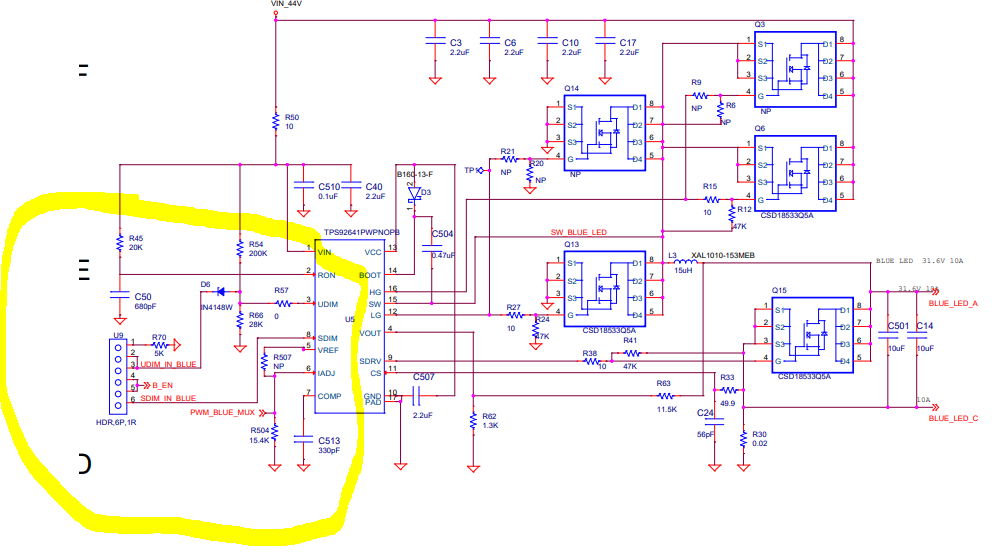
In the schematic, U9 is a 6 pin header that was intended to allow for easy measurements and also to allow the user to easily open/close the connections between the control signals and the driver.
You only need a jumper over pins 5 & 6 to connect the enable signals to the driver SDIM input. Same thing applies to Pins 1 and 2. Placing a jumper will ensure the driver is turned off when the other channels are on.