This thread has been locked.

If you have a related question, please click the "Ask a related question" button in the top right corner. The newly created question will be automatically linked to this question.

DLPLCR6500EVM: Impossible to start the DLP

Part Number: DLPLCR6500EVM

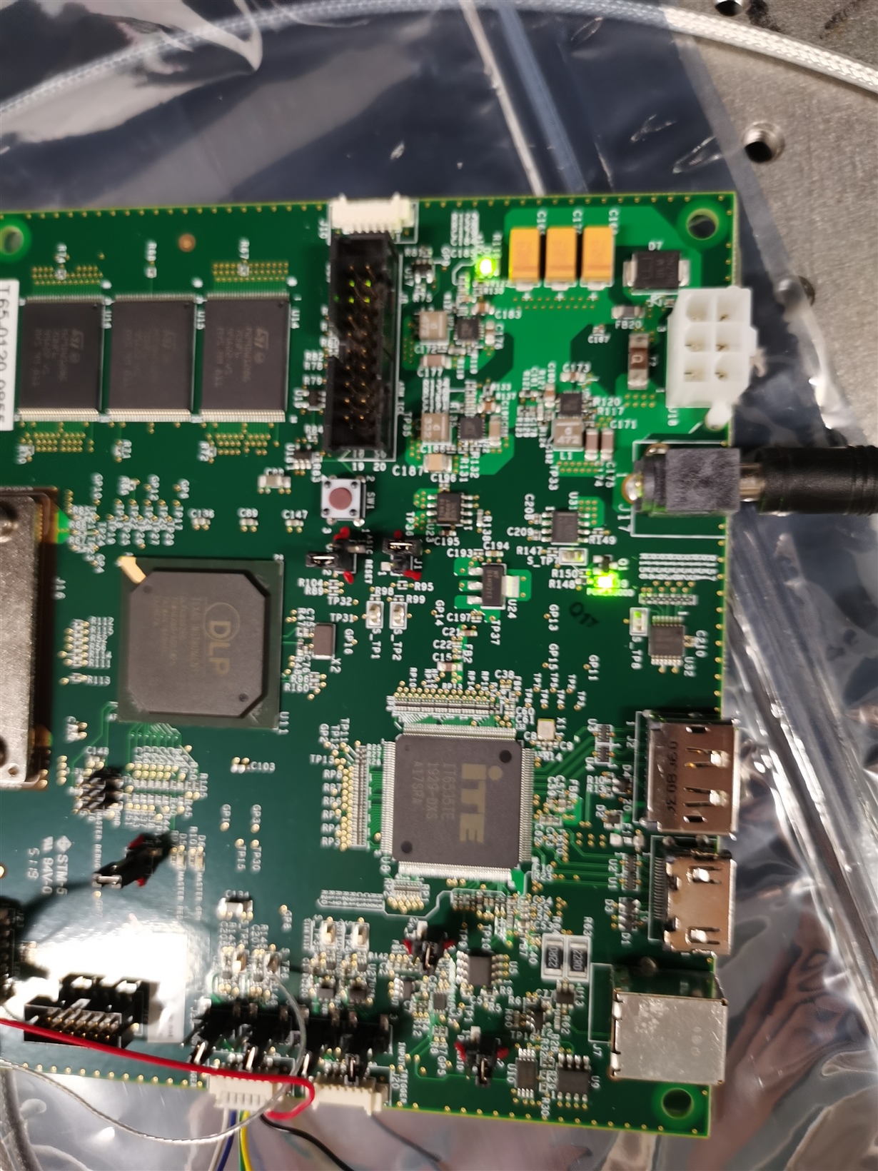
Today I want to test my DLP board, first time I start the DLP, it worked normally and displayed a continuous pattern sequence and I powered it off. However, when I tried to use it after several minutes, the DLP board can't start as before. D8 and D9 on the DLP light up green but D6 doesn't toggle on and off with the buzzer ringing. Cosequently, DMD always stay a still pattern. Besides, when I carefully remove the DMD from the socket, D6 start to toggle. Can you tell me what happened and how should I start the DLP board? Looking forward to your reply.
  • Supplementary:

     I also did same operation of reloading the firmware in

    https://e2e.ti.com/support/dlp/f/94/p/874525/3235758?tisearch=e2e-sitesearch&keymatch=DLP6500%252520boot%252520hold#3235758

    And I find 2 img files(dlp6500_09062020212432_firmwareimg.img & DLPR900PROM-6500-v5.0.1-OOB.img) and upload both of them one after another, but after removing the boot jumperand powering the kit back up, the same thing happened. DMD didn't display pattern and buzzer ring. What's more, I find that When I press reset switch(SW1), DMD mirrors seem to close and when I release SW1 all the mirrors seem to open and buzzer start to ring, does this mean DMD is normal but the DLP board can't drive DMD?

    Thank you in advance.

  • Hi Wenbin Jiao,

    Follow below steps and update result.

    1. Remove Power, Disconnect your connection from J24, Remove all the Jumpers.
    2. Place Boot hold Jumper.
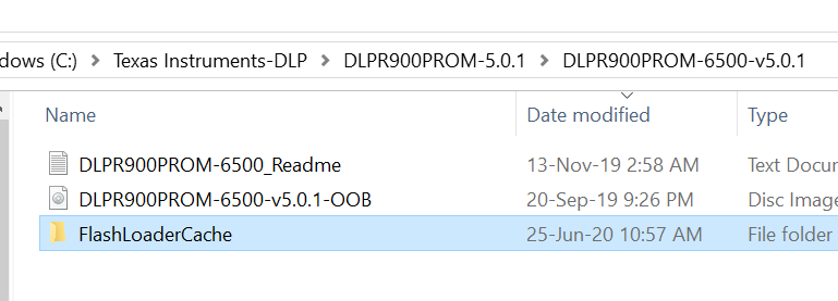
    3. Delete "FlashLoaderCache" Folder located in Firmware image folder.


    4. Power up the board, Open GUI, Select DMD as 6500 and load "DLPR900PROM-6500-v5.0.1-OOB" firmware image.
    5. Remove power, Remove Boot hold Jumper and Recycle power.
    6. D6 LED should start blinking.

    If not, you can capture Serial port debug logs at J6, Repeat above steps and share it for further analysis.

    Thanks,
    Shivakumar

  • Hi, Shivakumar.

    Thanks for your information, I did above steps but nothing happend that D6 can't toggle, buzzer still ring and fail to connect to PC. If I carefully remove the DMD from the socket, D6 start blinking and I can connect to PC successfully. By the way, can you tell me how to  capture Serial port debug logs at J6.

    Thank you in advance.

  • Hi Wenbin Jiao,

    Thanks for the update. Looks like something wrong with the placement of DMD. You can try with another DMD board and check if problem is repeated.
    Have you done any experiment or modifications on the DMD board. Please share its pictures.

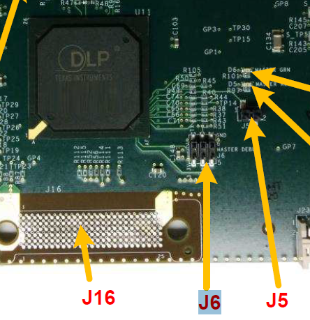
    Serial port outputs at J6 are 3.3-V TTL level and require an external transceiver to convert to RS232.
    Pin 2 is TX and Pin 6 is GND. 

    You need serial terminal software like "Terraterm" or "Putty".
    configure terminal with below settings.

    – Bits per second: 115200
    – Data bits: 8
    – Parity: None
    – Flow Control: None

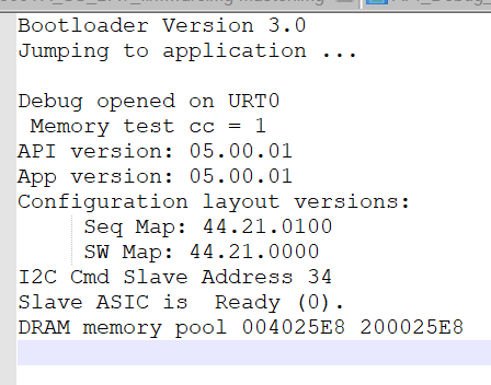
    If connections are made proper and Serial terminal software is configured proper, you can expect to see below message printed out when system boots. 

    Thanks,
    Shivakumar

  • Hi, Shivakumar.

    Thanks for your information. I put DMD to another control board as you said, then DMD can start up, display a continuous pattern and connect to PC normally. After EVM working for sevral minutes, DMD seems to be heating. Is this normal and I wonder whether it will damage DMD?

    I add some trigger wire at J24 on our original DMD board, I don't think it's the reason because the DMD work well after connecting trigger wire. I forgot to take some pictures and I will fetch it up tomorrow.

    I don't have a transceiver to convert J6 to RS232 now and I will post the Serial port debug logs after I get a transceiver. When using serial terminal software to debug, should I place Boot hold Jumper or just connect the PC with RS232 directly?

    Thanks for your patience in advance. Looking forward to your reply.

  • Hi Wenbin Jiao,

    No need to connect boot hold jumper.

    Does the DMD board has heat sink attached. Slight heating is expected while DMD is showing patterns.

    You can use similar TTL-232R-3V3 converter to capture serial debug logs.

    Thanks,
    Shivakumar

  • Hi Wenbin Jiao,

    Can you confirm how hot the DMD is getting?

    If nice and warm, but not excessively hot, that would be ok.
    But if very hot that could be a problem.

    There is an issue that can happen if the controller board is handled while running that tends to fry DMDs.

    Thanks,
    Shivakumar

  • Hi Shivakumar,

    Thank you again and sorry for replying so late. I have tried the DMD on another board for several minutes, it worked normally and DMD was not excessively hot. However, I still want to find the reason why the previous board can't control DMD. I bought a converter to capture serial debug logs, and I will reply as soon as possible if there any updates.

  • Hi Wenbin Jiao,

    Thanks for the Update.