This thread has been locked.

If you have a related question, please click the "Ask a related question" button in the top right corner. The newly created question will be automatically linked to this question.

DLPC3433: Boot Image Trouble

Part Number: DLPC3433
Other Parts Discussed in Thread: DLPA2005, , DLPDLCR3010EVM-G2, DLPA3000

We are trying to get our DLPC 3433 based board up and running.


We have downloaded the FWsel_DLPC3433_DLPA2005_pm1_i2c0x36_v7p4p2.exe file from the TI site and

programmed the associated binary image file into the SPI flash part.


When we boot the system we see a lot of activity on the SPI lines between the flash part and the 3433 for about

2 ms. Then it goes quiet.  The HOST_IRQ signal never goes low, regardless of whether there is a projector connected or not.


Also, we see a momentary flash (red), in the display, then darkness.


We have 2 questions:

1)      Does the pin mapping option effectively select a right vs. left projector cable pinout ?  If not can you please

clarify what that option controls?

2)      We are not sure what to investigate at this point. Can you make any suggestions as why the 3433 appears to

not be successfully booting?

UPDATE: 

We are seeing the HOST_IRQ signal go low for ~500uS, to indicate the DLP chip set has properly auto-initialized. Right when the HOST_IRQ signal goes low, the VLED voltage rises from ~4V to ~6.4V, indicating a most likely open LED (according to dlpa089a). During power up, we are noticing a brief flash of the red LED.


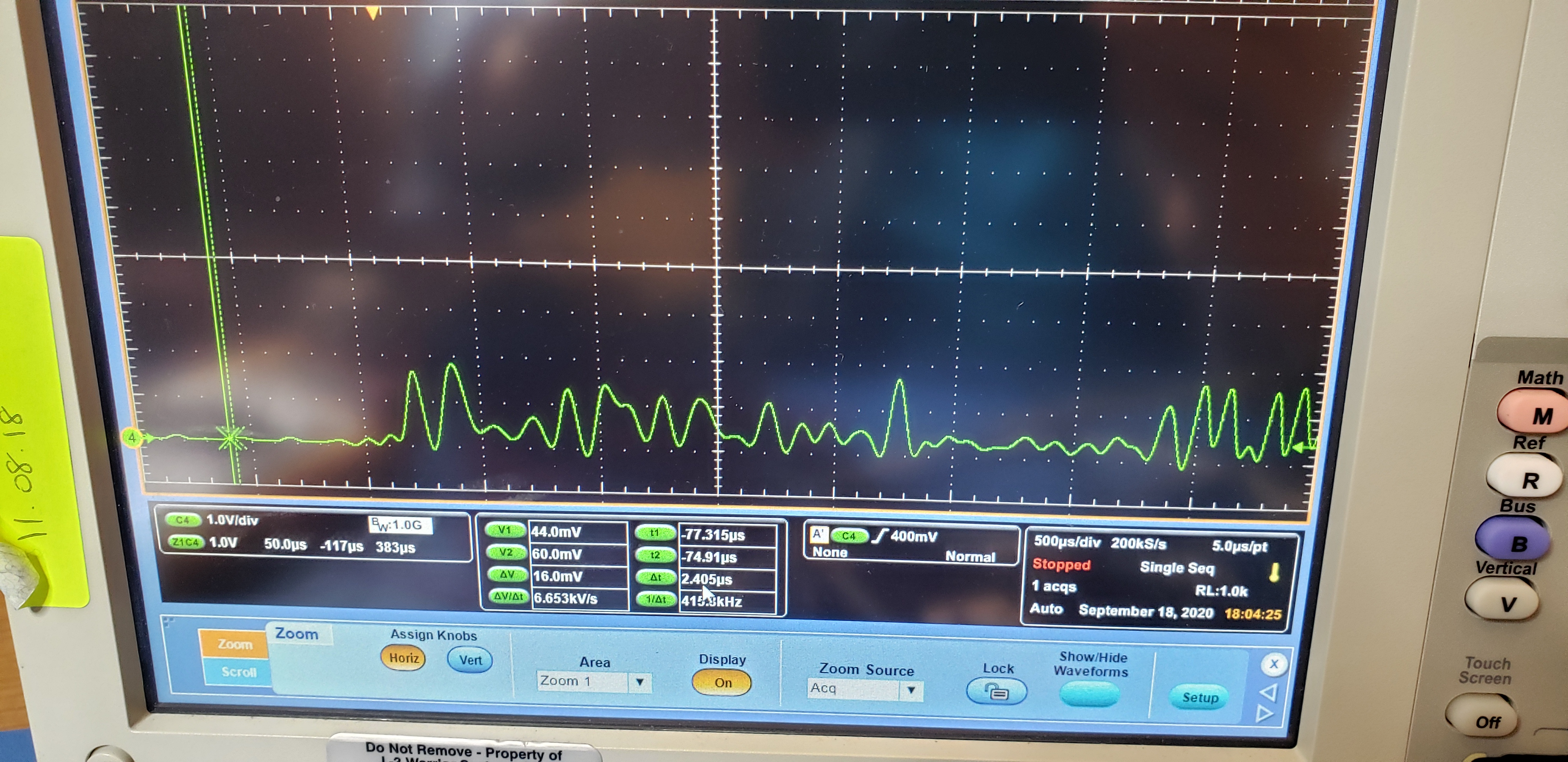
In addition, the DMD_LS_CLK signal integrity looks questionable (see attached picture). This is being measured directly at the DLPC3433.


We appear to be turning the supplies on in the correct order, and VOFS, VBIAS and VRST are at their appropriate value (for 200mS).

  • Hi Dean, 

    Welcome to TI E2E Forums!


    Looks like there maybe some HW issue with your setup. Can you please confirm the following?

    1. Your power supply is able to supply the required current to the EVM.

    2. Your schematic design strictly follows our reference design DLPDLCR3010EVM-G2.

  • Thank you for your response. I have received the follow from our engineering team. I also added them to this email for more direct communication.


    Engineering Response:


    We could not strictly follow the DLPDLCR3010EVM exactly because we are not using the DLPA3000.


    We also did not notice the LS drop below ~1.8V, so it appeared the system did not “brown out”.


    I would agree that it has to be something with the HW. Not much software it being used to turn this on.


    The DLPA2005 requires external LDO’s (going off of document dlpa089a). One is used for the load switch and the other for VINTF (VFLSH is being supplied from LS). In the referenced document, I am referring to section, 2.1 System Power Block Diagram. Maybe the LDO’s are being over-driven, but I am did not see any drop in the output voltage (I can look again).


    Our supply feeding the VINx for the DLPA2005 can handle up to 5A continuous. I don’t think that one is of concern.


    Respectfully,


    Dean Perrotta

  • Dean,

    Thanks for your input. Since you are using an optical engine that is different from the EVM's standard optical engine, you will need to verify your design with the OEM before proceeding.

    Please keep us in loop on the same. 

    Best Regards,

    Philippe Dollo