This thread has been locked.

If you have a related question, please click the "Ask a related question" button in the top right corner. The newly created question will be automatically linked to this question.

DLP4710LC: Does DLP4710 support incident illumination light path from the left side of DMD same as DLP3010?

Part Number: DLP4710LC
Other Parts Discussed in Thread: DLP4710, DLP3010,

Hi

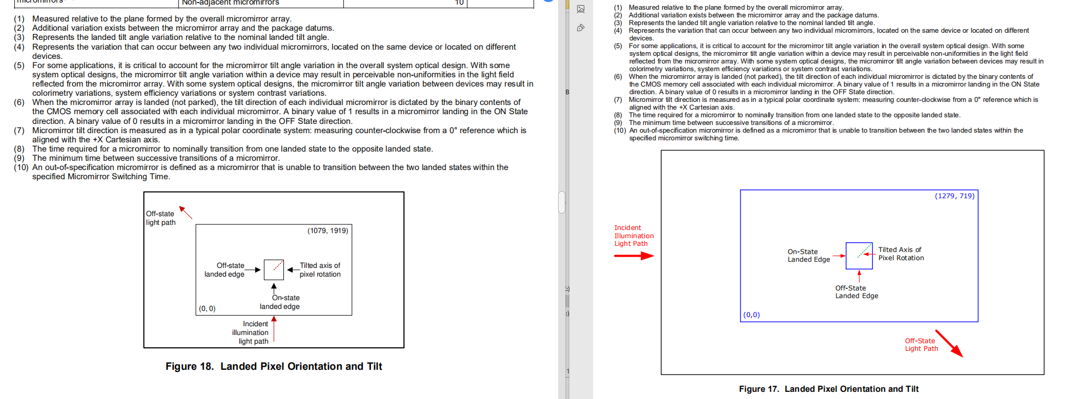
I found that DLP4710 and DLP3010 have the same mechanical structure and the same description . In there datasheets , DLP3010 has a On-state landed edge on the left side of the micro mirror and Off-state landed edge on the down side of the micro mirror . The incident illumination light path comes from the left side of the DMD chip and the Off-state light path goes through the bottom right side of DMD . But in DLP4710LCs description , the micro mirror of DLP4710 has an opposite state , on-state on the down side and off state on the left side . Does it mean we can flip the on and off state of DLP4710 mirror using " inver pattern Bits " option , and make it has the same on/off state as DLP3010 and let the incident illumination light comes from the left side same as DLP3010 too . If we can't use it this way , what is the reason ?

  • Hello,

    Based on your question, it sounds like you are asking if there any functional difference between a mirror in off-state versus on-state (aside from the angle of incidence). Is this correct?

    I'll verify and let you know.

    Regards,

    Philippe Dollo

  • Xu,

    The "ON" state and "OFF" states for the DMDs are not identical in this case. In particular, there is a "Pond of Mirrors (POM)" around the active pixels of the DMD which are kept in the OFF state and are not addressable by the DLP controller. This concept is discussed here: https://e2e.ti.com/support/dlp/f/94/t/30507 

    What this essentially means is, if you were to use a DMD that was "inverted" to use the OFF state mirrors as active pixels, you would end up with a bright border (from the POM) around the entire image that is fixed.

    I apologize for the inconvenience.

    Regards,

    Philippe Dollo

  • Hi 

    Thank you for your replying . 

    You mean this area between two line is POM area , and mirrors in this area will always in off-state , if we use off-state as on , this area will always be bright . Right ?

    Are there other problems if we use off-state as on-state except this POM issue ? 

    And by the way , I wonder why the incident illumination light path of DLP4710LC is designed from the down side not from the left side same as DLP3010 , what is the advantage ?

    Regards,

    Dianwei Xu

  • Hello Dianwei,

    You are right the POM will show bright line around the image if DLP4710 DMD is illuminated from the side. The following are the key difference of side vs bottom illumination:

    Side illumination - enables a thinner optical engine

    Bottom illumination - The prism used in in the optical engine is smaller may result in cost saving for prism and may smaller size for engine.

    Hope this answers.

    regards,

    Vivek