This thread has been locked.

If you have a related question, please click the "Ask a related question" button in the top right corner. The newly created question will be automatically linked to this question.

DLPC3433: DLPC3433 DSI route not working with Linux Kernel/DRM

Part Number: DLPC3433
Other Parts Discussed in Thread: DLPA3000

Hi,

We have Allwinner R16 based board designed with DLPC3433. I did follow the DSI setup, sequence and timings as mentioned in DSI guide for 854x480 resolution.

Linux DRM drivers has following details.

1. Bridge driver

    4, lanes

    MIPI_DSI_FMT_RGB888 format

    MIPI_DSI_MODE_VIDEO_SYNC_PULSE mode

   enabled PROJ_ON GPIO

    0xd7 = 0x0

    0x10 = 00 00 00 00 56 03 e0 01

    0x12 = 00 00 00 00 56 03 e0 01

    0x2e = 56 03 e0 01

    0xbd = c8 00

    0x05 = 0x00

    0x07 = 0x00

    0x52 = 0x07 /* for LED glow */

2. DSI Host

    Host blanking setup

    EOT enabled

3. Panel driver

    As per Example DSI Configuration and Timings from DSI Debug guide for 854x480

    .clock = 25905,

    .hdisplay = 854,
    .hsync_start = 854 + 10,
    .hsync_end = 854 + 10 + 3,
    .htotal = 854 + 10 + 3 + 7,

    .vdisplay = 480,
    .vsync_start = 480 + 4,
    .vsync_end = 480 + 4 + 3,
    .vtotal = 480 + 4 + 3 + 7,

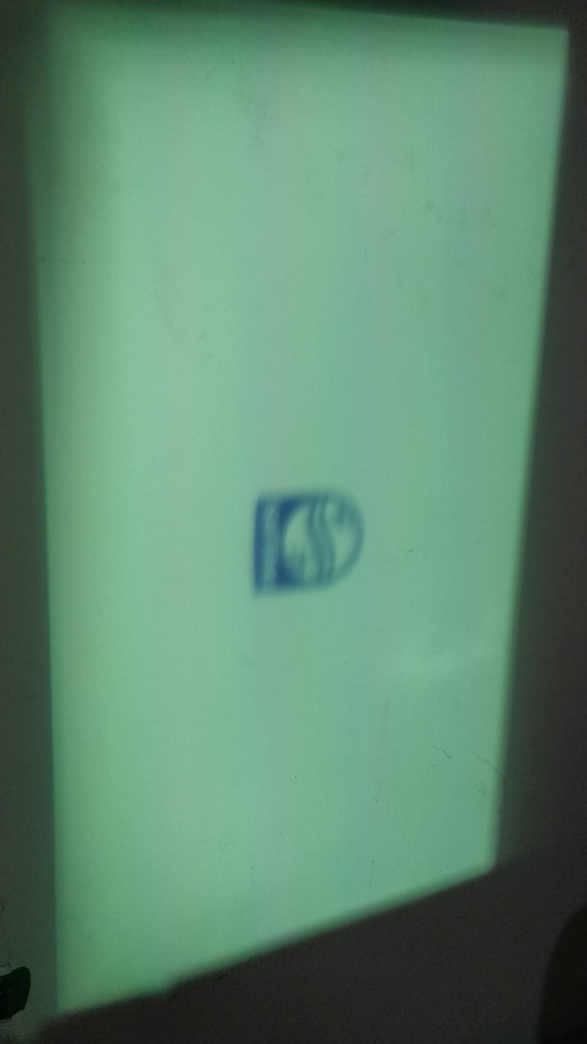
After setting all the above setup I can see LED glow in white centred with Philips logo however the excepted one should be Linux Penguins logo.  I can confirm that the same DSI host is working other DSI panels. and register values seems fine too.

Here is the regmap dump for register values to confirm.

Any help where it blocked?

Jagan.

  • Hello Jagan,

    Welcome back to the E2E forum.

    Is the Philips logo another video file that may be fed in, or is it a splash screen? If it is another video file, there may be an issue on your front end.

    Are you experiencing these same issues with a video at the DMD's full resolution (1280x720)?

    Regards,

    Austin

  • Hi Austin,

    I didn't feed Philips logo, expecting logo during Linux boot would be Linux Penguins. Seems like Philips logo is default splash screen. I wounder why would a splash screen logo appeared since register 05.1:0 is 00 ie External Video Port.

    What do you mean by front end issue?

    The DSI Debug Guide mentioned only 854x480 and I don't know relevant timings for 1280x720 if you have any I'm happy to test?

    Jagan.

  • Hi Austin,

    If you have a supporting PClk or Pixel clock for 1280x720, may be I would create some timings. Please pass it if you have any?

    Jagan.

  • Jagan,

    Are you able to check if the Philips image is saved as a splash screen in the firmware?

    Timings for 1280x720:

    Active pixels per line: 1280

    Active lines per frame: 720

    Lane count: 4

    Frame rate (time on wall): 60

    Burst mode: enabled

    Play mode: continuous

    Burst mode: events

    Hsync Blanking: HS mode

    HBPorch Blanking: Hs mode

    Vertical Blanking mode: LP11

    H Active (pix): 1280

    V Active (lines): 720

    HSync (pix): 3

    HBPorch (pix): 7

    HFPorch (pix): 10

    Vsync  (lines): 3

    VBPorch (lines): 7

    VFPorch (lines): 4

    PixClk (MHz): 57.333

    FPS (Hz): 60

    DSI Clk HS Freq (MHz): 230

    DSI Pixel Format: RGB565

    Please try these timings and let me know if the DSI feeds more readily. Naturally, these timings should be tried with 1280x720 images.

    Regards,

    Austin

  • Hi Austin,

    Thanks for the details.

    I'm unaware of firmware saving mechanism, any information on how to retrieve it.

    I did check your 1280x720 resolutions timings with Video Sync Pulse (MIPI_DSI_MODE_VIDEO_SYNC_PULSE) and RGB888. However the result seems to be same.

    Here are the detailed changes.

    1. Bridge driver

        4, lanes

        MIPI_DSI_FMT_RGB888 format

        MIPI_DSI_MODE_VIDEO_SYNC_PULSE mode

       enabled PROJ_ON GPIO

        0xd7 = 0x0

        0x10 = 00 00 00 00 00 05 d0 01

        0x12 = 00 00 00 00 00 05 d0 01

        0x2e = 00 05 d0 01

        0xbd = e6 00

        0x05 = 0x00

        0x07 = 0x00

        0x52 = 0x07 /* for LED glow */

    2. DSI Host

        Host blanking setup

        EOT enabled

    3. Panel driver

    .clock = 57333,

    .hdisplay = 1280,
    .hsync_start = 1280 + 10,
    .hsync_end = 1280 + 10 + 3,
    .htotal = 1280 + 10 + 3 + 7,

    .vdisplay = 720,
    .vsync_start = 720 + 4,
    .vsync_end = 720 + 4 + 3,
    .vtotal = 720 + 4 + 3 + 7,

    Is burst mode and RGB565 is mandatory setting? I need to check if DSI host is working with burst mode before checking DLPC.

    Jagan.

  • Jagan,

    I believe this was discussed in a separate thread linked here: https://e2e.ti.com/support/dlp/f/94/t/958518?DLPC3433-DSI-Burst-mode 

    In case you haven't already, be sure to check out the DSI setup and debugging guide here: https://e2e.ti.com/support/dlp/f/94/t/846660

    I hope this helps.
    Regards,

    Philippe Dollo

  • Hi Philippe,

    Yes. I'm understand the previous thread. I'm asking Austin about the timings he provided will able to work on non-burst and RGB888.

    Jagan.

  • Hi Austin,

    I have used working Panel timings for this particular DSI host from Allwinner with 800x480, Video Sync and RGB888. However result seems to be same, white screen with Phillips logo.

    +static const struct drm_display_mode ti_dlpa3000_mode = {

    + .clock = 30000,
    + .hdisplay = 800,
    + .hsync_start = 800 + 40,
    + .hsync_end = 800 + 40 + 48,
    + .htotal = 800 + 40 + 48 + 40,
    + .vdisplay = 480,
    + .vsync_start = 480 + 13,
    + .vsync_end = 480 + 13 + 3,
    + .vtotal = 480 + 13 + 3 + 29,
    +};

    +static const struct panel_desc ti_dlpa3000 = {
    + .modes = &ti_dlpa3000_mode,
    + .num_modes = 1,
    + .bpc = 6,
    + .size = {
    + .width = 154,
    + .height = 86,
    + },
    +};

    Any comments on above I2C configuration sequence? Did I missed any commands?

    Jagan.

  • Jagan,

    Thanks for your feedback and patience. Once the New Year's holiday is ended we should be able to provide input on the above. 

    Best Regards,

    Philippe Dollo

  • Hi Austin,

    I did tried the above code with I2C commands and here are my observations. Please note that, all timings are mentioned in DSI Debug Guide for 854x480 and RGB888 format with DSI HS clock of 200MHz.

    0x52 register for LEDS register update with initial image shows full white as

    Case-1: Test pattern 

    I2C_BUS=1
    I2C_ADDR=0x1d
    i2cset -y ${I2C_BUS} ${I2C_ADDR} 0x52 0x07 
    i2cset -y ${I2C_BUS} ${I2C_ADDR} 0x1a 0x01
    i2cset -y ${I2C_BUS} ${I2C_ADDR} 0x10 0x00 0x00 0x00 0x00 0x56 0x03 0xe0 0x01 i
    i2cset -y ${I2C_BUS} ${I2C_ADDR} 0x12 0x00 0x00 0x00 0x00 0x56 0x03 0xe0 0x01 i
    i2cset -y ${I2C_BUS} ${I2C_ADDR} 0x2e 0x56 0x03 0xe0 0x01 i
    i2cset -y ${I2C_BUS} ${I2C_ADDR} 0xbd 0xc8 0x00 i
    i2cset -y ${I2C_BUS} ${I2C_ADDR} 0x05 0x01
    i2cset -y ${I2C_BUS} ${I2C_ADDR} 0x1a 0x00

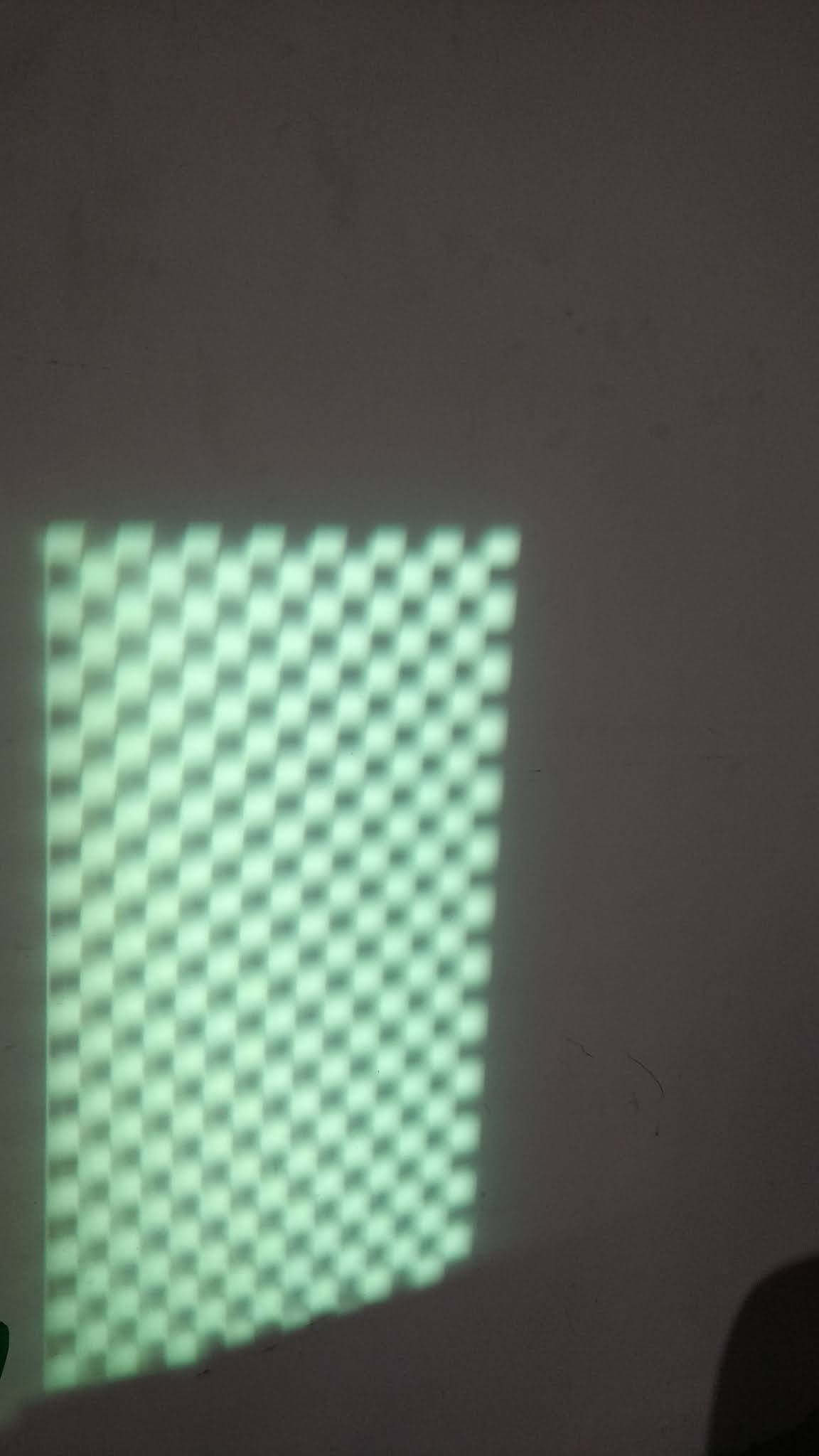
    Output: default checker board test pattern is shown in 854x480 resolution 

    Case-2: External Video Port (DSI)

    I2C_BUS=1
    I2C_ADDR=0x1d
    i2cset -y ${I2C_BUS} ${I2C_ADDR} 0x52 0x07
    i2cset -y ${I2C_BUS} ${I2C_ADDR} 0x1a 0x01
    i2cset -y ${I2C_BUS} ${I2C_ADDR} 0xd7 0x00
    i2cset -y ${I2C_BUS} ${I2C_ADDR} 0x10 0x00 0x00 0x00 0x00 0x56 0x03 0xe0 0x01 i
    i2cset -y ${I2C_BUS} ${I2C_ADDR} 0x12 0x00 0x00 0x00 0x00 0x56 0x03 0xe0 0x01 i
    i2cset -y ${I2C_BUS} ${I2C_ADDR} 0x2e 0x56 0x03 0xe0 0x01 i
    i2cset -y ${I2C_BUS} ${I2C_ADDR} 0xbd 0xc8 0x00 i
    i2cset -y ${I2C_BUS} ${I2C_ADDR} 0x05 0x00
    i2cset -y ${I2C_BUS} ${I2C_ADDR} 0x07 0x24
    i2cset -y ${I2C_BUS} ${I2C_ADDR} 0x1a 0x00

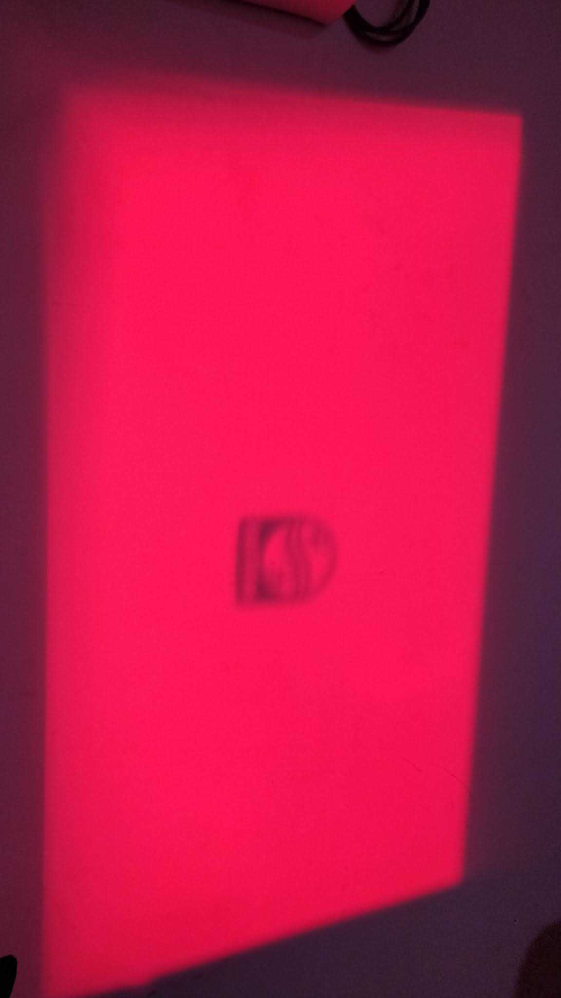
    Output: Orange coloured full image, and not follow 854x480 resolution.


    Sorry to attach big images, I couldn't find proper way to attach them. My intention is to explain the issue bit more elaborate.

    As we compare test pattern vs external DSI port, seems like DSI output is wrong or some firmware upgrade require or so. I'm expecting the same check board would appear for DSI with 854x480 resolution, let me know if my understanding is wrong.

    Request for further inputs.

    Jagan.


  • Jagan,

    Where did you get the firmware image that you are using? What image do you see if you choose splash as the input?

    The timings I previously provided will only work with RGB565 and burst event mode. While I realize you are looking for RGB888 resolution, I would like you to try the lower bit resolution to test if the DLPC3433 will treat a full 1280x720 resolution differently than the 854x480 resolution. Naturally, this will change the values of the 0x10, 0x12, and 0x2e registers.

    Are you able to try these settings to test the functionality of the controller?

    To answer a previous question, by "front end" I meant the source of the video information.

    Regards,

    Austin

  • Hi Austin,

    Any further inputs on this topic?

    Jagan.

  • Jagan,

    Have you seen my questions and suggestions above?

    Kindly,

    Austin

  • Hi Austin,

    I have believe I already mentioned about 1280x720 with RGB565.

    Here is the command snippet, result is same as I have mentioned. White screen with Philips logo.

    I2C_BUS=1
    I2C_ADDR=0x1d
    i2cset -y ${I2C_BUS} ${I2C_ADDR} 0x52 0x07
    i2cset -y ${I2C_BUS} ${I2C_ADDR} 0x1a 0x01
    i2cset -y ${I2C_BUS} ${I2C_ADDR} 0xD7 0x00
    i2cset -y ${I2C_BUS} ${I2C_ADDR} 0x10 0x00 0x00 0x00 0x00 0x00 0x05 0xd0 0x01 i
    i2cset -y ${I2C_BUS} ${I2C_ADDR} 0x12 0x00 0x00 0x00 0x00 0x00 0x05 0xd0 0x01 i
    i2cset -y ${I2C_BUS} ${I2C_ADDR} 0x2e 0x00 0x05 0xd0 0x01 i
    i2cset -y ${I2C_BUS} ${I2C_ADDR} 0xbd 0xc8 0x00 i
    i2cset -y ${I2C_BUS} ${I2C_ADDR} 0x05 0x00
    i2cset -y ${I2C_BUS} ${I2C_ADDR} 0x07 0x00
    i2cset -y ${I2C_BUS} ${I2C_ADDR} 0x1a 0x00

    I didn't touch any firmware, directly using the module from buyer.

    Jagan.

  • Jagan,

    From what has been posted here it appears that you have tried RGB888 but not RGB565. The DLPC3433 will not be able to process RGB888 with the timings and resolutions that I have provided.

    Are you able to test RGB565? If so, what can you observe when you send the video file with the DLPC3433 initialized?

    What appears when you select splash screen as the input? It would be convenient to know if the Phillips logo is, in fact, the splash screen or the video coming in correctly.

    Additionally, can you ensure that you are maintaing LP11 mode as delineated on page 37 of the DLPC3433 User's Guide? Are you able to observe these lines with an oscilloscope?

    Regards,

    Austin

  • Hi Austin,

    The above test has RGB565, isn't it? if you can see the source format command

    i2cset -y ${I2C_BUS} ${I2C_ADDR} 0x07 0x00

    0x00 means DSI RGB565

    I can confirm by reading read source format it's giving 0x21

    # i2cget -y ${I2C_BUS} ${I2C_ADDR} 0x08
    0x21

    Let me know if I miss anything here?

    I did test RGB565 with above command set, not feeding any video file. I'm expecting check board while setting external video port but it doesn't gave anything. Let me know whether it is correct behaviour or different.

    Let me know how to feed Video file, while testing via I2C commands.

    For splash screen and external video port result the same white screen, how test pattern gives check board image.

    I2C_BUS=1
    I2C_ADDR=0x1d
    i2cset -y ${I2C_BUS} ${I2C_ADDR} 0x52 0x07
    i2cset -y ${I2C_BUS} ${I2C_ADDR} 0x1a 0x01
    i2cset -y ${I2C_BUS} ${I2C_ADDR} 0xD7 0x00
    i2cset -y ${I2C_BUS} ${I2C_ADDR} 0x10 0x00 0x00 0x00 0x00 0x00 0x05 0xd0 0x01 i
    i2cset -y ${I2C_BUS} ${I2C_ADDR} 0x12 0x00 0x00 0x00 0x00 0x00 0x05 0xd0 0x01 i
    i2cset -y ${I2C_BUS} ${I2C_ADDR} 0x2e 0x00 0x05 0xd0 0x01 i
    i2cset -y ${I2C_BUS} ${I2C_ADDR} 0xbd 0xc8 0x00 i
    i2cset -y ${I2C_BUS} ${I2C_ADDR} 0x05 0x00 # DSI no response, white screen
    i2cset -y ${I2C_BUS} ${I2C_ADDR} 0x07 0x00
    i2cset -y ${I2C_BUS} ${I2C_ADDR} 0x1a 0x00
    i2cset -y ${I2C_BUS} ${I2C_ADDR} 0x1a 0x01
    i2cset -y ${I2C_BUS} ${I2C_ADDR} 0x05 0x02 # splashscreen no response, white screen
    i2cset -y ${I2C_BUS} ${I2C_ADDR} 0x1a 0x00
    i2cset -y ${I2C_BUS} ${I2C_ADDR} 0x1a 0x01
    i2cset -y ${I2C_BUS} ${I2C_ADDR} 0x05 0x01 # test pattern, white screen become check boards
    i2cset -y ${I2C_BUS} ${I2C_ADDR} 0x1a 0x00

    Sorry, I don't have oscilloscope with me to verify LP11, any other ways to validate that.

    Jagan.

  • Hi Austin,

    Any further comments would be helpful.

    Thanks,

    Jagan.

  • Jagan,

    Did you make the timing and resolution changes to the video feed as well?

    You will need to test this with a video feed. The DLPC3433 will not have data to display otherwise.

    Regards,

    Austin

  • Hi Austin,

    Can you describe the procedure to do that while testing via I2C command set.

    Jagan.

  • Hi Austin,

    Any further update on this?

    Linux driver has same behaviour that above I2C command sequence with 1280x720, RGB565, Burstmode, EOT, LP11. 

    It would be better to understand working behaviour via I2C command set first. Once it is fine, I will try to check the same in Linux.

    Jagan.

  • Jagan,

    The I2C commands that you have posted here should be sufficient for the DLPC3433 to display the DSI video feed.

    The video timings should be set up, but not sent before the DLPC3433 boots. Once HOST_IRQ signal has gone low, the I2C commands you have posted should be executed and the DLPC. Then the video data should be switched from LP11 mode to the clock and data as specified in the DSI debug guide.

    Can you confirm that the video feed is being fed properly?

    For questions regarding the video feed source, you may wish to reach out to the company that manufactured the DSI generator.

    Regards,

    Austin

  • Hi Austin,

    Thanks for your confirmation on I2C command sequence. I have question that how can we feed video timings via I2C command set since we are feeding only hdisplay and vdisplay no Pclk or porch values?

    About video feed, cannot we do that via I2C or some tool on Linux console instead of DSI generator. Right now getting DSI generator from the manufacture seems difficult.

    Apart from this, Which DSI host this DLPC3433 has been tested? this can give me some information to check respective host driver in Linux Kernel. Or any related information regarding testing platform on Linux would be really appreciated.

    Jagan.

  • Jagan,

    There may be some confusion on the above.

    The DSI bus on the DLPC3433 does not work unless there is a good video stream coming in. As a matter of fact, the DSI mode on this chipset is naturally baked into the external video mode (provided you configured the I2C registers mentioned by Austin correctly) and the DSI mode is then "enabled" via autoswitch when a valid DSI video feed is provided.

    If you hooked up the external video input to "nothing" the DLP system's output will hang on whatever the last good image was (typically a splash or test pattern). 

    In the case of DSI, you must both configure the I2C registers on the DLPC3433 as well as provide a valid DSI signal. If you are not getting a DSI video output when everything is connected together, you would want to suspect first the DSI video feed itself, and then the DLPC3433.

    If you are having issues per the above, you could probably start by verifying with a known good sink that your DSI video signal is good. If you can confirm that your DSI signal is good, then you should then confirm that the I2C registers on the DLPC3433 are OK. If both of these are good but you are still not able to get it working, you may need to relax your DSI timings in the case that the DLPC3433 cannot handle the timings that you tested your DSI with originally.

    I hope this helps.
    Regards,

    Philippe Dollo

  • Hi Austin, Philippe,

    Thanks for your inputs and time.

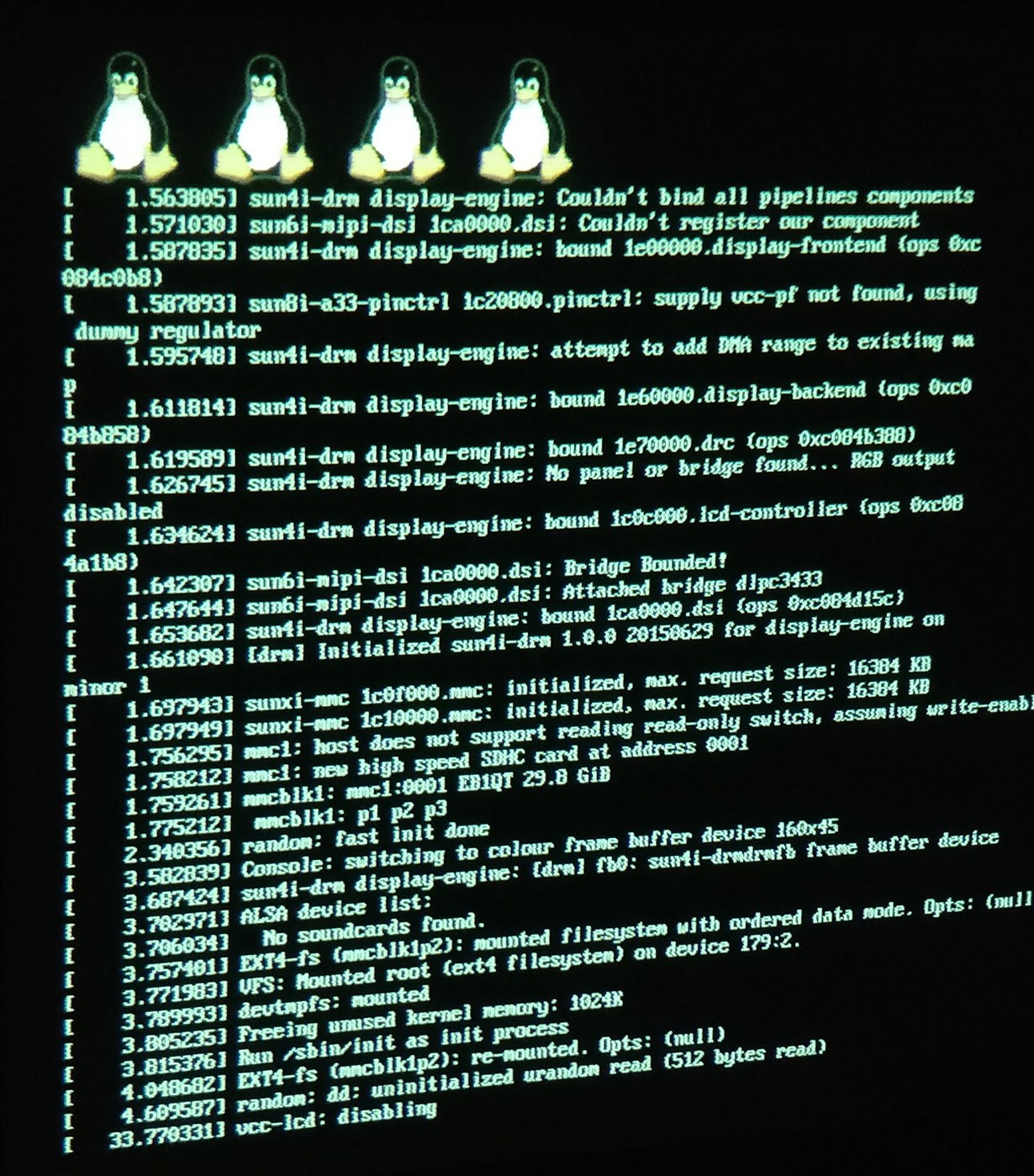
    I finally able to boot the Linux via DLPC Projector, means I can see Linux booting logs on wall and trying to boot Ubuntu distribution.

    1. DSI timings for 1280x720 has adjusted with respect to supporting PClk in Allwinner R16

    2. RGB888 is working, RGB565 is not working. Not sure why you mention RGB88 is unsupported in DLPC3433.

    Here is the Linux bootlog on wall.

  • Jagan,

    I am glad to hear that your DSI feed is projecting properly.

    In another E2E thread, Philippe and I mention that the DLPC3433 does not support 32-bit formats. The DLPC3433 will, however, support RGB888 (a 24-bit format). I had suggested trying to use the RGB565 as the timings that I had available were verified with the 16-bit format. This suggestion was primarily meant to observe a behavior of the board as opposed to establishing a final bit resolution.

    Kind regards,

    Austin

  • Austin,

    Sorry for the wrong interpretation. Yes I have tested RGB888 24-bit, indeed it is working, However 16-bit RGB565 cannot work as properly as RGB888 but I can see black lines and Linux Frame buffer is responding too.

    Jagan.

  • Jagan,

    Is the screenshot above for RGB888 video? It looks a bit fuzzy so I am curious whether your timings are solid for this particular system configuration.

    You may want to try to optimize these timings first. If necessary, you could try reducing your resolution to relax clock requirements until you get the interface working.

    Regards,

    Philippe Dollo