Other Parts Discussed in Thread: DLPC900
Hello,
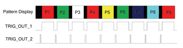
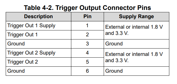
I am trying to measure the output triggers for my DLP6500 DMD, indicated as J24 pins 1 and 2 in the TI User Guide. From what I understand, J24 pin 1 should be high when the mask is on (for the exposure time duration) and low when the mask is off (for the dark time duration and if the dark time is 0us, then this output will remain high). J24 pin 2 should have a 20us pulse at the beginning of a new mask (indicating the transition from the previous mask to the new mask). I see that you can also invert these signals and set a time delay for the rising and falling edges.
I am using an Arduino for input triggering and to measure the trigger outputs from the DMD. I have the J24 pin 2 connected to the Arduino analog voltage input A3 (as seen in the photos) so I would expect to see a 20us pulse for every mask change (if the Arduino time resolution is good enough) but instead when the dark time is set to 0us I see a constant high voltage and when there is a non-zero dark time I see a high voltage corresponding to the exposure time and low voltage corresponding to the dark time. This is what I would expect to see from J24 pin 1, is there any way the user manual pins are swapped? I am currently unable to read the J24 pin 1 voltage.
Initially, I thought J24 pin 1 and 2 could be connected through excess solder, but from visual inspection and an electrical test, it does not seem that they are connected.