This thread has been locked.

If you have a related question, please click the "Ask a related question" button in the top right corner. The newly created question will be automatically linked to this question.

DLP9000BFLS: Persistent vertical line artifacts after image upload error

Part Number: Part Number: DLP9000BFLS
Other Parts Discussed in Thread: DLPC900

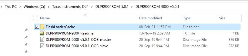
We are using a 3DLP9000 UV Light Engine controlled by the Lightcrafter 9000 EVM which uses 2 DLPC900's in a master-slave configuration. Recently we noticed that the projection area corresponding to the master DLPC900 illuminates with a faint background artifact image. We do not recognize the image displayed. This faint background image displayed changes slightly depending on what is being projected, but largely stays the same. Resetting to default DLI or TI firmware does not solve the issue. One example image, when we project an example provided image file with a single dot (which displays correctly as you can see):

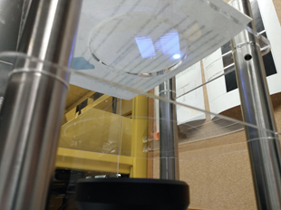
Another example image taken from a UV camera shows streaking lines crossing through the pattern.

The artifact was first observed after a pattern/image upload which caused an error. The upload was attempted from the GUI we are developing based on the API used by the DLP Lightcrafter DLPC900 GUI.

The Master DLPC900 red fault status LED was pulsing indicating an internal fault in the controller. The fault was identified as 4 critical error pulses, 1 module error pulse. The following is the UART debug log from connection to the error occurs:

Debug opened on URT0

Memory test cc = 1

API version: 05.00.01

App version: 05.00.01

Configuration layout versions:

     Seq Map: 44.21.0100

     SW Map: 44.21.0000

I2C Cmd Slave Address 34

Slave ASIC is  Ready (0).

DRAM memory pool 004025E8 200025E8

ptn_seq.c (1014) >> Failed

Illumination: Transition to operating mode

 Configuring LED Enable and PWM Driver...

 PWM Driver initialized...

 Setting PWM Drive Levels...

Controller Product ID: 06

DMD Type: 7a

DMD Product ID : 24

System Mode: There are 1 defined System Modes

System Mode: System Mode 0 supports 2D

Sysmon: Executing Default Batch file

Illumination: Transition to operating mode

 Configuring LED Enable and PWM Driver...

 PWM Driver initialized...

 Setting PWM Drive Levels...

*** Data abort near 00001a54 ***

"Data abort near 00001a54" is where the error occurs, but "ptn_seq.c (1014) >> Failed" may be where the persisting artifact is coming from. "ptn_seq.c (1014) >> Failed" also shows up on the debug log when just using the provided DLP Lightcrafter DLPC900 GUI. Could this be from some corruption caused by the error we are encountering?

The following is a log of the commands sent to the DLPC900C through USB (3 images/patterns attempted to be sent):

1A1B : Set on the fly mode

1A34 : Define Pattern (x3)

1A31 : Pattern Config

1A2A : Init BMP Load (Master)

1A2B : BMP Load (Master

1A2C: Init BMP Load (Slave)

1A2D: BMP Load (Slave)

0101 : Read Error Code Description

0101: Read Error Code Description

After the error occurred, the system was reset, either through disconnecting the power brick from the outlet or hitting the reset button on the board. Upon rebooting the system, the error disappeared. The artifact was first observed during the next projection experiment after the error had occurred and has persisted since. 

The light engine and board have been mounted for several weeks now and have not moved, so we do not think that the EVM flex cables have been damaged.

  • Hi Tim,

    Thanks for sharing detailed error information. Debug log captured will be useful to find the root cause.

    *** Data abort near 00001a54 *** error indicated that Controller is trying to access invalid memory location.

    Please try out below steps and update the result. Keep capturing UART debug log while doing this operation. 

    • First Delete the flash loader cache folder,
    • Upload the Out of Box firmware(DLPR900PROM-9000-v5.0.1-OOB). This will erase entire flash memory and upload the firmware fresh.
    • Check if Internally stored patters are cycling properly. Check for Data abort error.

  • Shivakumar,

    Thank you for your assistance. We have tried the steps you recommended and the vertical line artifact still persists. 

    Here is a debug log from a startup and test run after uploading the OOB firmware.

    Debug opened on URT0

    Memory test cc = 1

    API version: 06.00.00

    App version: 06.00.00

    Configuration layout versions:

         Seq Map: 90.00.0000

         SW Map: 90.00.0000

    I2C Cmd Slave Address 34

    digcontrol_init complete: 1

    Slave ASIC is  Ready (0).

    thinapp : Goto State : 2 0

    DRAM memory pool 004025E8 200025E8

    Autolock initialization passed

    Picture Control: Default System Mode 0

    thinapp : Display mode 1 0

    Displaying Video Curtain...

    Illumination: Transition to operating mode

     Configuring LED Enable and PWM Driver...

     PWM Driver initialized...

     Setting PWM Drive Levels...

    Controller Product ID: 06

    DMD Type: 7a

    DMD Product ID : 24

    System Mode: There are 1 defined System Modes

    System Mode: System Mode 0 supports 2D

    Sysmon: Executing Default Batch file

    thinapp : Goto State : 10 1

    thinapp : Display mode 2 -1

    Displaying Dummy Splash Image

    Index = 0 Imageindex = 0 Bitindex = 0

     Index = 1 Imageindex = 0 Bitindex = 8

     Index = 2 Imageindex = 0 Bitindex = 16

     Index = 3 Imageindex = 1 Bitindex = 0

     Index = 4 Imageindex = 1 Bitindex = 8

     Index = 5 Imageindex = 1 Bitindex = 16

     Index = 6 Imageindex = 2 Bitindex = 0

     Index = 7 Imageindex = 2 Bitindex = 8

     Index = 8 Imageindex = 2 Bitindex = 16

     Index = 9 Imageindex = 3 Bitindex = 0

     Index = 10 Imageindex = 3 Bitindex = 8

     Index = 11 Imageindex = 3 Bitindex = 16

     Index = 12 Imageindex = 4 Bitindex = 0

     Index = 13 Imageindex = 4 Bitindex = 8

     Index = 14 Imageindex = 4 Bitindex = 16

     Index = 15 Imageindex = 5 Bitindex = 0

     Index = 16 Imageindex = 5 Bitindex = 8

     Index = 17 Imageindex = 5 Bitindex = 16

     thinapp : System Powerup complete

    thinapp : Goto State : 8 0

    thinapp : Display mode 1 0

    Displaying Video Curtain...

    Autolock Enable : 1

    ALC Event: 0-2

    Event: Source Lost.

    thinapp : Goto State : 5 0

    thinapp : Display mode 1 0

    Displaying Video Curtain...

    Autolock Enable : 0

    thinapp : Goto State : 6 0

    thinapp : Display mode 0 0

    Displaying Test Patterns...

    Index = 0 Imageindex = 0 Bitindex = 0

     ptn.c (1304) >> Failed

    thinapp : Goto State : 8 0

    thinapp : Display mode 1 0

    Displaying Video Curtain...

    Autolock Enable : 1

    ALC Event: 0-2

    Event: Source Lost.

    thinapp : Goto State : 10 3

    thinapp : Display mode 2 -1

    Displaying Dummy Splash Image

    Autolock Enable : 0

    Index = 0 Imageindex = 0 Bitindex = 0

     thinapp : Goto State : 3 1

    thinapp : Goto State : 4 1

    Illumination: Disable Illumination

    Illumination: Transition to Standby Mode comlete

  • Hi Tim,

    Do you still face Data aboard error with OOB firmware?

  • Shivakumar,

    We are not facing the data abort error with OOB firmware. However, we are still seeing vertical line artifacts in the projection image. 

    Thanks,

    Tim

  • Hello Tim,

    Are you able to measure (in pixels) the distance from one line artifact to the next one? 

    This type of artifact is typically the result of a poorly connected or not connected single LVDS line.  Please check the Controller and DMD board pads for the flex cables for debris on the pads - clean as necessary.  Also check the flex cable pins for damage or debris on the pins. If there is debris, clean as necessary.  If pins are damaged, the flex cable will have to be replaced (or repaired).  Damaged flex cable pins is not common.

    Also check the DMD connection pads on the DMD board and the interposer between the DMD and DMD board for any missing, damaged, or rotated "C" springs (i.e. connectors in the interposer).

    After this please carefully reconnect the cables and DMD and test again.

    Fizix

  • Thank you for your suggestions, we tried going through those steps and were not able to resolve the problem. The line artifacts are 32 pixels apart.

    We will be sending the light engine back to DLI for repairs.

    Could it be possible that the data abort error caused by the controller trying to access an invalid memory location could damage the DLPC900?

    Thanks,

    Tim

  • Tim,

    The data abort error does not damage the DMD.  The fact that they are 32 pixels apart is almost certainly a problem with a single data line.  The hardest issue to spot is if one of the "C" springs in the interposer becomes rotated so that it does not appear to be missing, but is not making contact with the pads on the DMD board and/or the DMD.

    DLi should be able to get you rolling again.

    Fizix