This thread has been locked.

If you have a related question, please click the "Ask a related question" button in the top right corner. The newly created question will be automatically linked to this question.

DLP6500FLQ: TriggerOut2 has a variable amplitude

Part Number: DLP6500FLQ


The output of the trigger Out 2 has a varying amplitude, Therefore it is difficult to read this trigger.

We measured the voltage to be around 1V with maximum of 1.5 V

Is there some problems with the DMD or it could be a problem with my commands?

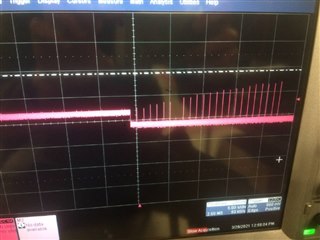
It appears that the initial continuous pattern has 3.3V amplitude but then with the pattern that I am sending the trigger  has an amplitude of 1V or less.

  • It looks like your scope is only running at 50kS/s; that should be one sample every 20us.  I believe the trigger pulses are 20us in duration, so you might only get a single sample in every trigger.  You may need to adjust your oscilloscope sample rate to be something like 1MS/s to be sure you see a reasonable representation of the trigger pulses.  

    I assume you have a DLP® LightCrafterTm 6500 EVM. If you refer to section 1.5 of the EVM user's guide, you will find details on how to select the trigger input and output voltages using J19, J21, J22, & J25.  https://www.ti.com/lit/ug/dlpu028d/dlpu028d.pdf 

    I hope that helps.

    Regards,
    Gary

  • Thank you for the very quick response.You are right I am using the  DLP® LightCrafter 6500 EVM and I am indeed quite sure that I configured the trigger output 2 correctly (trigger output 2 marks the beginning of each pattern start with 20 μs pulses). I aim to use this to trigger another board that accepts a TTL input as the trigger.

    I took your advice and changed the sampling rate and it did help. I have a stable output. But the issue is that the patterns that are displayed by default when the DMD is initialized give a trigger value of around 3V while the set of patterns that I load on to the DMD give a trigger  that fluctuates between 1.5 and 0.5V(find images below for both the cases). The manual says the following about the amplitude that can be expected from this trigger output.

    Triggers during initial continous pattern

    Trigger of the patterns that I uploaded

    I do not understand the reason behind this fluctuation in the voltage of the trigger pulse. Could you help me in this regard?

    Also, as I mentioned earlier the board I want to trigger accepts a TTL input. Does this mean that I need an adapter to convert DMD output to a TTL ? If yes, could you suggest me the necessary adapter.

    Thanks a lot in advance.

    Bossi

  • 5V TTL Inputs typically have the same switching thresholds as 3.3V TTL; so the 3.3V TTL output of the EVM likely can drive your TTL input.

    NOTE: The trigger inputs on the EVM are NOT 5V tolerant; so you should NOT input a 5V TTL signal into the EVM trigger inputs. (They are only tolerant to 4.6V.)

    Do you have Jumpers across pins 1-2 on J22 and J25?   

    You can confirm the Trigger I/O voltage is set to 3.3V by measuring from J24 pin 6 (gnd) to pin 4 (Trigger 2 Vcc) and pin 1 (Trigger 1 Vcc).  You should see 3.3V on these if you have the jumpers selected to 3.3V.

    The triggers are digital outputs; they can only output 3.3V or 1.8V. 

    If you are seeing something else, it is likely you have a measurement problem.  I could simply be that the time base your oscilloscope is configured for cannot display such narrow pulses.  Try changing to something like 100 uS/div and trigger on a rising edge at 1.5V.  Do you see what you expect to see in that case? 

    Good Luck.

    Regards,
    Gary