This thread has been locked.

If you have a related question, please click the "Ask a related question" button in the top right corner. The newly created question will be automatically linked to this question.

eZdsp C5535 teaching ROM

Other Parts Discussed in Thread: TMS320C5535

Hello,

I've been trying to go through the teaching ROMS using the C5535 eZdsp I purchased recently and have been having trouble using a microphone with the board.  I have been following the wiki in order to port them to the C5535, found here: http://processors.wiki.ti.com/index.php/Porting_C5000_Teaching_ROM_to_C5535_eZdsp.

More specifically, I've been trying to work through lesson 2.  The first lesson in directly porting the input to the output line worked fine, and in this lesson you are supposed to work with changing the gain and sampling frequency.  When I choose what the lesson suggests for a line input, it works (48kHz, 30db), but I cannot hear the microphone working, using any setting.  I have verified that the microphone works using my computer, but through the C5535 I can hear nothing.  Are there any suggestions that you can give?  

Thanks!

Sherwin

  • Hi Sherwin,

    See http://e2e.ti.com/support/dsp/tms320c5000_power-efficient_dsps/f/109/t/140749.aspx#611327

    I suspect you need to enable the MIC_BIAS to use your PC (electret) microphone.

    The Teaching ROM labs used dynamic microphones, which do not require a bias current. There is a picture of one in the Presentation Slides.

    Add two instances of the following line in aic3204_init.c:

        /* ADC ROUTING and Power Up */
        AIC3204_rset( 0, 1 );      // Select page 1
        AIC3204_rset( 51, 0x48);  // power up MICBIAS with AVDD (0x40)or LDOIN (0x48)    //MM add mic bias
        AIC3204_rset( 0x34, 0x10 );// STEREO 1 Jack

    You may want to reduce the gain from 30dB also.

    Hope this helps,
    Mark

  • I just added the instructions for configuring a microphone as input to the C5535 eZdsp to the Porting C5000 Teaching ROM to C5535 eZdsp wiki page...

    http://processors.wiki.ti.com/index.php/Porting_C5000_Teaching_ROM_to_C5535_eZdsp#Configuring_a_Microphone_as_Input_to_the_C5535_eZdsp

    Regards,
    Mark

  • Hello Mark,

    Thanks for your quick response.  I went ahead and added the mic bias to the aic3204_init.c file, as you posted above both trying the 0x40 and 0x48 values as well as differing gain values as well as 12kHz sampling frequency (I hadn't done this before because I didn't know normal PC microphones were electret microphones).  However I still heard nothing from my microphone that I confirmed working using the computer's sound card.  I have tried with both a headset I purchased and the headset included in the USB dev. kit.  I tried with a reduced gain of 15 dB as well as a higher 48 dB but still nothing came through.  I am assuming the sound that comes through the input will have slight lag.  

    Again thanks for the quick response!

    Thanks,
    Sherwin Yeo 

    PS Just noticed your second response while typing this up, I'll look at what you posted and let you know if it worked.

  • I got it to work, thanks so much!  I found out that I had only added the line to the first function and not the second function as well, which the wiki makes clear.  Thanks for the help!

    Sincerely,
    Sherwin  

  • Great!

    I'm glad you were able to get the microphone input to work.

    Regards,
    Mark

  • Hi,

    I have been following this thread because Ive had trouble powering a "stereo" microphone. I have made the required changes as mentioned above... and I am only able to power half of the microphone, if that makes any sense.  the microphone I am using is actually two different microphones that tie into a single TRS connector... each microphone is tied to a respective channel (left or right). The reason I am working with this microphone is because a two microphone array is required and the C5535 ezdsp does not have two input jacks.

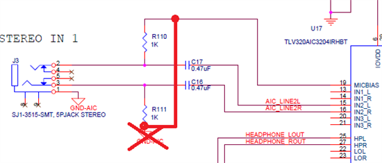
    As far as the on-chip hardware is concerned, I noticed that only ONE channel is powered at all times with the default voltage is 1.25V. I looked at the schematics and it looks like  IN2_L (of the codec) is the only line being powered via MICBIAS. Is the only way to power IN2_R to tie it to IN2_L? If this is the case... this might be an issue because the R&L signals would mix. Any knowledge of this issue?

    Sincerely,
    Jef 

  • Hi Jef,

    Without board modification, your stereo microphone will only half work - only one channel (left channel) receives MIC_BIAS...

    To get stereo mic input to work, remove R111 connection to GND-AIC and blue-wire it to MICBIAS (CODEC side of R110) through a 1k resistor.

    This way both R110 and R111 have a 1k resistor path to MICBIAS.

    Hope this helps,
    Mark

  • Hi,

    I've done all the above modifications to the code but it still doesn't work. I get no errors when I build the project 1, I can debug it as well but when I run the code I get this message in console: 

    PLL frequency 100 MHz
    REGISTER --- CONFIG VALUES

    and I hear nothing.

    any idea what I'm doing wrong?

    Thank you

    Sina

  • Hi,

    The expected console output is shown below...

    PLL frequency 100 MHz
    REGISTER --- CONFIG VALUES
    PLL_CNTRL1   8be8 --- 8be8
    PLL_CNTRL2   080e --- 0806 Test Lock Mon will get set after PLL is up
    PLL_CNTRL3   8000 --- 8000
    PLL_CNTRL4   0000 --- 0000

    Running Getting Started Project
    <-> Audio Loopback from Stereo IN --> to HP/Lineout
    Sampling frequency 48000 Hz Gain =  0 dB

    I have attached the .out file of Chapter 1 for you to load onto your board and run.

    http://e2e.ti.com/cfs-file.ashx/__key/communityserver-discussions-components-files/109/8625.Chapter1_2D00_5535.out

    I have verified playback using MP3 player as the input and headphones as output.

    Also check that the C5535 DIP Switch is in the following configuration:

    1: OFF - CLK_SEL low - RTC oscillator is clock source

    2: ON - UART_BUFF_EN low - Enable UART signals to XDS100 VCP (not required)

    3: OFF - AIC3204I2C_ENn low - Enable I2S, MCLK, RESET signals to codec

    4: ON - SPI_CS_SW connected - SPI_CS0 signal connects to SPI Flash

    Hope this helps,
    Mark

  • I loaded the .out file onto my board but still I get the same output.

    Run=>Load=>Load Program, is that the right way to do that?

    Thank you

    Sina

  • Yes, that is the correct way to load the program...

    I just tried it without any GEL file defined in the target configuration, and the program ran correctly - it configures the PLL in the program.

    It seems strange that your console shows the first printf but not the next few on consecutive lines in PLL.c...

        printf("REGISTER --- CONFIG VALUES\n");

        printf("PLL_CNTRL1   %04x --- %04x\n",pllCfg1.PLLCNTL1,hPll->pllConfig->PLLCNTL1);
        printf("PLL_CNTRL2   %04x --- %04x Test Lock Mon will get set after PLL is up\n",
                                    pllCfg1.PLLCNTL2,hPll->pllConfig->PLLCNTL2);
        printf("PLL_CNTRL3   %04x --- %04x\n",pllCfg1.PLLINCNTL,hPll->pllConfig->PLLINCNTL);
        printf("PLL_CNTRL4   %04x --- %04x\n",pllCfg1.PLLOUTCNTL,hPll->pllConfig->PLLOUTCNTL);

    I even tried it with the incorrect CLK_SEL DIP switch setting, and my console output all of the above printf statements... (audio playback did fail with CLK_SEL high)

    Seems like a problem setting the PLL.

    Have you seen any other issues when using GEL files? Can you measure the frequency of the CLKOUT pin after connecting in CCS?

    You are using C5535 eZdsp, correct?

    I would check all voltages... (CVDD, DVDDIO, VDDA_PLL, DVDDRTC, CVDDRTC, etc)

    Does the eZdsp correctly run the USB Audio Class out of box demo?

    Regards,
    Mark

  • Mark! thank you for the quick response.

    I set the DIP switch setting as you said in the previous reply but again...
    No, this is my first time encountering such issue, I've worked with F28335 board and didn't have any problem at all.

    Yes, on the package it's written TMS320C5535 eZdsp I even checked the board itself and it's TMS320C5535 eZdsp.
    Yes it correctly runs the USB audio class. Sound is okay, OLED works perfectly.

    I can check the frequency as you asked tomorrow when I have a Multimeter.


    Appreciate it.
    Sina.

  • Hi Sina

    I got the same problem and solved it....... After many hours!!

    >:(

    The problem arise from the ..... Connected Audio Framework!!

    :-)

    When you buy the c5535 ezDSP the "Connected Audio Framework" is already on the SD card in the form of a file named bootimg.bin.

    When the ezDSP is plugged to the J1 USB then it receive a reset and boot from the SD.

    Then you start CCS, create a project from the first example of the TI Rom, compile and load "your compiled app" in the dsp.

    Then you start the debugger it and nothing goes as expected ....
    The symptom is the missing initialization strings in the console, so you get: 

    PLL frequency 100 MHz
    REGISTER --- CONFIG VALUES

    While the correct output should continue with


    PLL_CNTRL1   8be8 --- 8be8
    PLL_CNTRL2   080e --- 0806 Test Lock Mon will get set after PLL is up
    PLL_CNTRL3   8000 --- 8000
    PLL_CNTRL4   0000 --- 0000

    ...... etc.

    The debugger won't work, hang or shows just assembler code.

    What really happen is unknow to me, i may just suppose that in some way the initial boot from the SD card interfere with the loading of our project to the DSP.

    Anyway my solution was to create a bootimg.bin of a different program, I  used one from the TI Rom itself.

    You configure CCS to compile for Release (it is easy as for Debug options) then you convert your out file to bin using an utility.

    Look at this thread, there is a clear explanation on how to use hex55.exe to build a SD bootable app:

    http://e2e.ti.com/support/dsp/c5000/f/109/p/161606/590389.aspx#590389

    Then you copy this new image to the SD and restart the ezDSP card.

    The debugger will start correctly and you will be able to step thru the code (for wichever application... not just for that on the SD!!)

    :-)

    In case you want to restore the original content of the SD of the "connected audio framework" it is in the path:

    C:\c55\C55_Connected_Audio_Framework_EZDSP\c55-connected-audio-framework_binaries\CSL_USB_IsoFullSpeedExample_ezdsp_Out_bootimg

    Beware:  if the SD card is blanked (formatted) then the 5535 ezDSP card (with the configuration switch SW3 set as factory) is unable to boot and

    will not be recognised by the computer USB..... so it will not run the "connected audio framework" demo!

    Dhu! :-)

  • Thank you , that solved the problem.

    Regards,

    Sina.

  • Happy to have been useful to you  Sina :-)