This thread has been locked.

If you have a related question, please click the "Ask a related question" button in the top right corner. The newly created question will be automatically linked to this question.

Hex6x tool error: is this a bug in tool or a mistake in using it ?

Hi Ti.

    I'm using hex6x.exe from compiler 7.4.1(and the same result in compiler 7.4.8). After I processed the dsp0core3.out with it, I found that some data in the load get distorted with 2 bytes of 0 inserted. The way I call hex6x is :

hex6x -order L boot_script0.rmd  dsp0core3.out 

  The rmd is as below:

-a
-boot
-e 0x10800000
-order L

ROMS
{
  ROM1:  org = 0x0000, length = 0x1000000, memwidth = 32, romwidth = 32
	       files = { boot_code0.btbl }
}

And the origin data in .out  is as below figure:

The data with 0 inserted is as below:

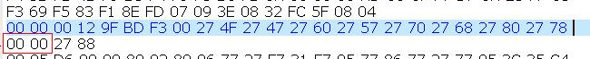
You can see 2 bytes of 0 in the middle.

All the files are included in the attachment so you guys may try it yourself. 4380.hex_err.rar

  • Hi,

    hex utility operation is clearly explained in C6000 assembly manual document. Please refer the document for more information.

    Thanks,

  • Hi Dhandapani.

       I had read that document before I post this. I don't find any clue in the document. And we have use hex6x to convert the .out files in this way for several years. It always works fine until we feeding this .out file in attachment to it. Would you please shed some light here? Thanks.

  • The hex utility has not made any errors.  At least, none that I can see here.

    I think you know the boot table format, but it bears repeating here.  The description I use comes from the section titled Boot Table in the C6000 assembly language tools manual.  Each section in the boot table has these contents:

    • 4-bytes for the size
    • 4-bytes for the address
    • raw data
    • 0-3 bytes of padding with 0 to align to a 4-byte boundary

    As you'll see, this padding accounts for the extra 0 bytes.

    The section of interest is named .tdScdmaCacheableDdrSeg.  The raw data for this section begins at file offset 0x0011ab40, as shown in the first image capture above.  The target memory address is 0x9fbdf300.  It is 0x12 bytes long.  Note this is 2 bytes short of a 4-byte aligned length.  

    I'll repeat the hex utility output for this section here, but broken up into 4-bytes per line.

    00 00 00 12
    9F BD F3 00
    27 4F 27 47
    27 60 27 57
    27 70 27 68
    27 80 27 78 
    00 00 27 88
    

    Line 1 is the length.  Line 2 is the address.  Lines 3-7 contain the raw data.  Note it is byte swapped versus how it is shown in the first image capture above.  This is because the option -order L is used.  This option means the data is written in little endian order: least significant byte first.

    Line 7 is key.  The two raw data bytes for this line are 0x88 0x27.  Two bytes of 0 are added.  Then those 4 bytes are swapped into little endian order.  That gives the final order of bytes used.

    Thanks and regards,

    -George

  • Hi George.

      You're right. The tool's behavior is correct. Thanks for your detailed explanation.