This thread has been locked.

If you have a related question, please click the "Ask a related question" button in the top right corner. The newly created question will be automatically linked to this question.

DM3730 GPMC_A1 sticking high

Other Parts Discussed in Thread: DM3730

Hi,

I am using the TI DM3730.   I cannot get my Dual UART chip to work ( Exar XR16L2751 ).

The Dual UART is connected to the DM3730's GPMC bus.  It is using GPMC_[A1:A3] for addresses and GPMC_[D0:D7] for data.  I noticed that I cannot read back the correct Device ID from the Dual UART chip, even though I have followed the procedure exactly as outlined in the datasheet.

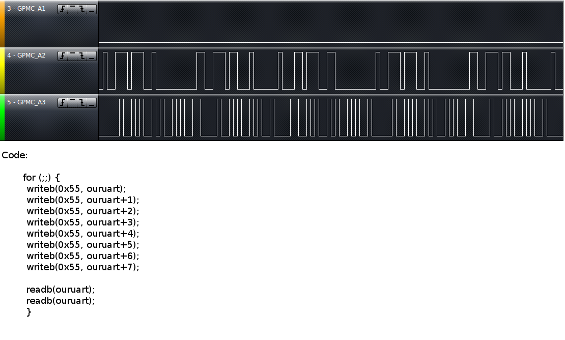
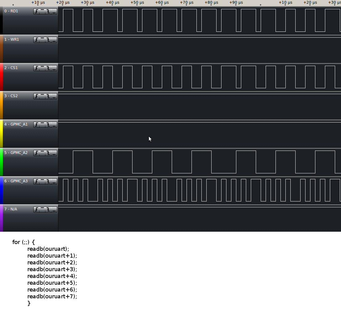
It seems there is something wrong with the address lines.  A loop through all the address values causes the A2:A3 lines to flicker up and down as they should, but A1 to stick high.

I did not know how to set the GPMC_CONFIG[1:7]_i registers (pg. 2193 of TRM) correctly.  As a "shot in the dark" I borrowed the values from another u-boot boardfile using a similar (but not same) UART chip.  I have a feeling that incorrect values here have caused my GPMC_A1 to stick high.  Or is it something else?

Could anyone point me in the right direction?  Thankyou!!!


  • Did you check whether the pin is muxed as GPIO? Check the register value of "0x4800 2078" and see whether the last 3 bits are zero.

  • Hi Renjith,

    If I use u-boot to check the contents of register 0x4800 2078 I get: 00180100

    From userspace I also read the value as: 0x00180100

  • Hi Andrew,

    Can you send me the value of the register 0x4800 207C? Also can you set 0x4800 2078 to 0x100? and see whether any change is there or not?

  • Hi Renjith,
    Thanks very much for your help so far.

    Register 0x4800 207C reads "0x00180018"  from within u-boot and userspace.

    I changed register 0x4800 2078 to 0x100 and the Exar Chip ID is still being read back incorrectly.  I also tried looping through all the address values again, and the GPMC_A1 line is still stuck.

    Open to any ideas at all, as I am completely stumped!

  • I have attached an image of the logic output of the OMAP's GPMC_[A1:A3] pins along with the code I used, in the hope that it may help.


  • Hi Andrew,

    Is it possible to share the portion of schematics with me? You can mail it to renjith.thomas@pathpartnertech.com.

  • Schematic portion sent!

    - Andrew

  • Just in case anyone is interested; here are the GPMC_config registers, when I read them from u-boot and kernel space.

    The kernel only appears to modify the seventh register.  Everything else stays as I set it.

    U-boot, GPMC_CONFIG[1:7]4:
    6e000120: 00001000    ....                                                                                        
    6e000124: 001f1f01    ....                                                                                      
    6e000128: 00080803    ....                                                                                           
    6e00012c: 1d091d09    ....                                                                                      
    6e000130: 041d1f1f    ....                                                                               
    6e000134: 00000fcf    ....                                                                                    
    6e000138: 00000000    .... 

    Kernel, GPMC_CONFIG[1:7]4:
    Value at address 0x6E000120 (0x40249120): 0x1000
    Value at address 0x6E000124 (0x40137124): 0x1F1F01
    Value at address 0x6E000128 (0x402d9128): 0x80803
    Value at address 0x6E00012C (0x400f812c): 0x1D091D09
    Value at address 0x6E000130 (0x40118130): 0x41D1F1F
    Value at address 0x6E000134 (0x4026a134): 0xFCF                                   
    Value at address 0x6E000138 (0x400a0138): 0xF41   

  • Andrew,

    Looks like your CONFIG7 value is completely wrong. Are you using CS4 for UART-A and CS6 for UART-B?

    First can you dump CONFIG7 values of all eight chip selects and see whether there is any overlap?

    Which are the addresses that you use to access the Dual UART or what is the value of the variable "ouruart"?

  • Hi Renjith,

    Correct. I am using CS4 for UART-A and CS6 for UART-B.  However, we have not written any code for CS6 in our board file, because we are not using UART-B.

    Here are the CONFIG7 values for each of the eight chip selects (as read from kernel space):
    0x6E000078 (cs0): 0x870
    0x6E0000A8 (cs1): 0xF00
    0x6E0000D8 (cs2): 0xF00
    0x6E000108 (cs3): 0xF00
    0x6E000138 (cs4): 0xF41
    0x6E000168 (cs5): 0xF6C
    0x6E000198 (cs6): 0xF00
    0x6E0001C8 (cs7): 0xF00

    The value of ouruart is: 0xe0808000.  But this is a virtual address which comes after ioremap.  The address before ioremap is 0x01000000.

    -Andrew


  • Andrew,

    I'll analyze these settings and update you.

    Meanwhile can you send me the waveform with the following lines?

    GPMC_A1, A2, A3, RD1, WR1, CS1, CS2. 

    Also have you access the address from u-boot and saw the waveform?

    Regards,
    Renjith 

  • Andrew,

    Got it. CONFIG1 should be 0x0 instead of 0x1000, as you are configuring the interface to 16-bit instead of 8-bit. Try this and let me know.

  • Hi Renjith,

    Here are the captures you requested.  Thanks very much for taking a look.
    I changed CONFIG1 to 0x0, but unfortunately, it had no effect.

  • Andrew,

    I'll take a look at it on Thursday and get back to you as I'm bit held up. Hope this is fine with you.

  • Hi Andrew,

    If you look at the A2 and A3 lines waveform there is a difference. The period of A2 in the first image(during read) is totally inverted in case of write. Ideally it should be same as address access is same. 

    So, could you please send me the complete code including in the macro definitions of readb() and writeb() and the pre-processor output generated(-E option)? If this is not a macro, could you please send me the assembly code generated (-S option)? 

  • Andrew,

    Where exactly did you put the probe? Which resistors/pads?

  • Hi Renjith,

    My apologies for the long period without a response.  The situation has changed a little.

    I am able to read the Device ID from within userspace, but only if I multiply the address by 2.  For example register 0x02 becomes 0x04,  register 0x03 becomes 0x06, etc.  The printk statements I posted earlier (alongside the logic analyzer signals) still do not work.

    I have noticed that the driver (drivers/serial/8250.c) does not give a printout telling me about my UART chip unless I write UPF_SKIP_TEST in my boardfile.  If I use UPF_SKIP_TEST, I get the dmesg printout, but my serial port cannot work at all.  UPF_SKIP_TEST skips the following test:

    if (!(up->port.flags & UPF_SKIP_TEST)) {
                     serial_outp(up, UART_MCR, UART_MCR_LOOP | 0x0A);
                     status1 = serial_inp(up, UART_MSR) & 0xF0;
                     serial_outp(up, UART_MCR, save_mcr);
                     if (status1 != 0x90) {
                             DEBUG_AUTOCONF("LOOP test failed (%02x) ",
                                            status1);
                             goto out;
                     }
             }

  • With regards to the above code, if I place a printk() below

    status1 = serial_inp(up, UART_MSR) & 0xF0;

    status1 will return as 0x00.  It also returns as 0x00 from userspace.  The device ID (0x0A) can be read from within userspace and the loopback test also works from within userspace.

    It would appear that this problem isn't related to the OMAP, but somewhere else.  I have checked the routing extensively (data lines, address lines, crystal, etc), and nothing appears to be wrong there. 

    What a huge headache!  Thankyou for your patience and support so far Renjith.  I really appreciate it.

  • Hi Andrew,

    I think now you have to change the offset of all UART register to be multiplied by two or you can just modify the funcitons serial_in or serial_out to do the shift. Hope you've already taken care of this.