This thread has been locked.

If you have a related question, please click the "Ask a related question" button in the top right corner. The newly created question will be automatically linked to this question.

DVO2 color bar on DM385

Other Parts Discussed in Thread: DM385, TVP5158

Hello everyone:

I have a customized board, ipnc_psp_arago package 04.04.00.02 on DM385 platform.

I want test on LCD display color bar, my LCD is connect to DVO2, 8bit line : VOUT0_G_Y_YC[2] ~VOUT0_G_Y_YC[9]

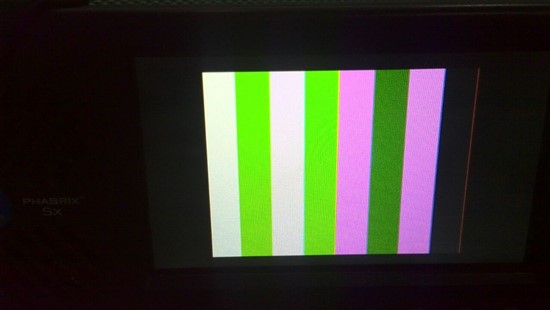
480i color bar display 

The color is wrong, could expert can help me? or any suggest.

my config value please refer below. Thank you very much.

--------------------------------------------------------------------------------------
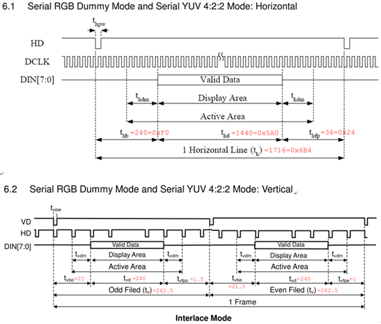
LCD spec :

its work on YUV 4:2:2, Interlace Mode
Number of Dots (HxV) 960 x 240 Dot

Horizontal:
ITUR601-NTSC Timing:
CLK 27 Mhz,
Horizontal Display Active 1440 CLK
Horizontal Line 1716 CLK
HSYNC Pulse Width 1 CLK
Horizontal Back Porch 240 CLK
Horizontal Front Porch 36 CLK
Horizontal Dummy Time 4 CLK

Vertical:
Vertical Display Active 240 Line
Vertical Total Time 262.5 Line
VSYNC Pulse Width 1 CLK
Vertical Back Porch
1. Odd Field 21 Line
2. Even Field 21.5 Line
Vertical Front Porch
1. Odd Field 1.5 Line
2. Even Field 1 Line
Vertical Dummy Time 0 Line

Latch data edge : Positive Edge
HD Polarity : Low pulse
VD Polarity : Low pulse
YcbCr se-quence : CbYCrY

--------------------------------------------------------------------------------------

DVO2 cfg register value

/usr/bin/mem_rdwr.out --wr 0x4810A004 003F0275
/usr/bin/mem_rdwr.out --wr 0x4810A008 1EA500BB
/usr/bin/mem_rdwr.out --wr 0x4810A00c 1F9901C2
/usr/bin/mem_rdwr.out --wr 0x4810A010 1FD71E67
/usr/bin/mem_rdwr.out --wr 0x4810A014 304001C2
/usr/bin/mem_rdwr.out --wr 0x4810A018 FF200200
/usr/bin/mem_rdwr.out --wr 0x4810A01c 1B6C0B35
/usr/bin/mem_rdwr.out --wr 0x4810A020 1C0C0C30
/usr/bin/mem_rdwr.out --wr 0x4810A024 1C0C0C30
/usr/bin/mem_rdwr.out --wr 0x4810A028 00271360
/usr/bin/mem_rdwr.out --wr 0x4810A02c 3F150018
/usr/bin/mem_rdwr.out --wr 0x4810A030 3F2D0089
/usr/bin/mem_rdwr.out --wr 0x4810A034 00000139
/usr/bin/mem_rdwr.out --wr 0x4810A038 0003F32D
/usr/bin/mem_rdwr.out --wr 0x4810A03c 042D008A
/usr/bin/mem_rdwr.out --wr 0x4810A040 00019008
/usr/bin/mem_rdwr.out --wr 0x4810A044 01120151
/usr/bin/mem_rdwr.out --wr 0x4810A048 01001120
/usr/bin/mem_rdwr.out --wr 0x4810A04c 0100213A
/usr/bin/mem_rdwr.out --wr 0x4810A050 0013913B
/usr/bin/mem_rdwr.out --wr 0x4810A054 042D0082
/usr/bin/mem_rdwr.out --wr 0x4810A058 00019008
/usr/bin/mem_rdwr.out --wr 0x4810A05c 01120152
/usr/bin/mem_rdwr.out --wr 0x4810A060 01001120
/usr/bin/mem_rdwr.out --wr 0x4810A064 0100013A
/usr/bin/mem_rdwr.out --wr 0x4810A068 00000000
/usr/bin/mem_rdwr.out --wr 0x4810A06c 00000000

echo 0 > /sys/devices/platform/vpss/display1/enabled

echo 27000,1440/36/240/1,480/1/21/1,1 > /sys/devices/platform/vpss/display1/timings
echo doublediscrete,yuv422spuv,0/0/1/1 > /sys/devices/platform/vpss/display1/output
echo 1 > /sys/devices/platform/vpss/display1/enabled

/usr/bin/mem_rdwr.out --wr 0x4810A000 0x4420B05C  // enable color bar

  • The echo command should send the number of active pixels and not the number of pixel clocks.

    echo 27000,1440/36/240/1,480/1/21/1,1 > /sys/devices/platform/vpss/display1/timings

    The highlighted should be 720 i believe. the clock doubling is handled by the format specifier.

    Additionally, the numbers do not match what you said for the LCD specification. You say 960x240 interlaced but then use 720*2 (=1440).

    You are also setting the vertical resolution to 240 but specifying interlaced. You need to check with the LCD datasheet EXACTLY what input format it can accept.

    I think you have quite a few things incorrect here but the LCD datasheet should clarify how things need to be set. Does the datasheet mention ITU656 (BT656) or some similar standard format for the interface?


    Finally the horizontal numbers don't add up correctly in the spec. What is 'dummy' time?

    BR,

    Steve

  • Hi steve, Thanks you for your reply.

    I fix the echo command :

    echo 0 > /sys/devices/platform/vpss/display1/enabled
    echo 27000,960/36/240/1,240/1/21/1,0 > /sys/devices/platform/vpss/display1/timings
    echo single,yuv422spuv,0/0/1/1 > /sys/devices/platform/vpss/display1/output
    echo 1 > /sys/devices/platform/vpss/display1/enabled

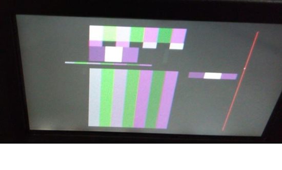
    but now LCD diplay below:


  • Try 720. As I mentioned previously there is something wrong with the LCD specification numbers.

    In one place it says 960 pixels but then in another it says total clocks per line = 1716. With an 8 bit interface each pixel needs 2 clocks so 960 pixels needs at least 1920 clocks which is greater than the specified 1716.

    I think you need to check back with the LCD manufacturer for a more complete/correct datasheet.

    BR,

    Steve

  • Hi Steve,

    You are right about the LCD spec.

    My coworker integrated DM36x and this LCD successfully.

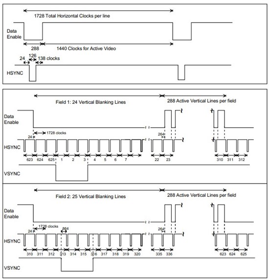
    He suggests me to implement the “Serial YUV422 mode” (BT601) timing followed:


     The latest register dump is :

    0x4810a000 45A0B059
    0x4810a004 003F0275
    0x4810a008 1EA500BB
    0x4810a00c 1F9901C2
    0x4810a010 1FD71E67
    0x4810a014 304001C2
    0x4810a018 FF200200
    0x4810a01c 184C0C77
    0x4810a020 1C0C0C30
    0x4810a024 1C0C0C30
    0x4810a028 8420D6B3
    0x4810a02c 010A6016
    0x4810a030 015A00EE
    0x4810a034 00000139
    0x4810a038 00038338
    0x4810a03c 015A00F0
    0x4810a040 00015000
    0x4810a044 000F0015
    0x4810a048 010000F0
    0x4810a04c 01000000
    0x4810a050 00000000
    0x4810a054 015A00F0
    0x4810a058 00015000
    0x4810a05c 000F0015
    0x4810a060 010000F0
    0x4810a064 01000000

    And the wrong color bar is :

  • Could you possibly send me the LCD datasheet/ I think something is not configured on the LCD.

    It looks like the LCD might be expecting serial RGB instead of serial YUV422.

    BR,

    Steve

  • Steve

    LCD spec is attached.

    Its maker is lnnolux (not TOP) now.

    BTW. we use LCD's default power on register settings as the I2C-like control I/F are disconnected.

    0880.990000270 (LCJ025T003A) Spec V1 1-2009-01-05.pdf

  • First, I would suggest always connecting the control interfaces to any external devices. This would be useful in debugging this issue.

    OK, make sure that the H-sync and V-sync polarities being output from the DM385 are correct. They should be set to negative.

    Make sure that the DM385 is configured to transition output data on the positive edge of the data clock since the LCD captures on the falling edge bu default.

    If possible connect the I2C for the LCD so that you can experiment with LCD parameters, in particular register 3 bits 3:2 which control the expected format ordering.

    BR,

    Steve

  • Steve

    The LCD timing chart is attached.

    Is it right ?

    1817.LCD_SCOPE.tar.gz

  • Steve

    I have inversed the data clock, but the color is same.

  • I think this is an LCD mis-configuration but it is very difficult to debug remotely.

    Try inverting the H-sync polarity.

    Try increasing the horizontal front porch by 1 whilst decreasing the back porch by 1. This shouldn't make a difference but it may shift the relationship between Y & C.

    BR,

    Steve

  • Hi Steve,

    Thank you for your suggest, I will try to configure LCD.
    then response to the result.

    BTW. The LCD interface is spi, I tried enable spidev on user space but fail.
    can you help me about this ? Thank you again.
    http://e2e.ti.com/support/dsp/davinci_digital_media_processors/f/716/t/314145.aspx

  • Unfortunately I do not know wnything about the software side of things.

    BR,

    Steve

  • Hello Steve

    The color bar now is corrected.

    but I need set the LCD YCbCr sequence register: YCrYCb
    BT 656 standard YCbCr sequence should be CbYCrY.
    why the DM385 output do not meet ? or have register can be set ?

  • I think this is most likely a mis-alignment between the 2 devices.

    The DM does output a standards compliant 656 stream, but incorrect h-sync parameter settings can shift the apparent phase.

    I recommend checking that all pixels are being displayed correctly by displaying a single pixel wide outer box and making sure you can see all outer edge pixels correctly.

    BR,

    Steve

  • Hi Steve

    Please let me know the register address that can change the pixel clock polarity of DVO2 ?

    My HDVPSS document is "SPRUH17 December 2012"

    Thanks in advance. 

  • Hi vic lin:

        I've meet the issue same with you on DM385,Can you post me the detail modifications to get the correct color bar?

        thanks very much!!!

    ST

  • Hi sunnyT.

    I think this is helpful, please let me know the result.

    /usr/bin/mem_rdwr.out --wr 0x48100114 0008010D # CLKC VidEnc Clk Sel

  • Hi vic lin:

        Thanks for your replay.

        There is no video output<black screen> when i set 0x48100114 to 0x0008010D. The original value of the reg is 0x9010d.

        Can you post the VPSS register configuration to me?

    BR

    ST

  • Hi sunnyT:

    you should be set register 0x48100114 to 0x0008010D is when color bar display on LCD. can you try again ?


  • Hi sunnyT:

    below posted my DOV2 reg setting info, I hope helpful for you.


    echo 0 > /sys/devices/platform/vpss/display1/enabled
    echo 27000,720/18/119/1,240/20/1/1,0 > /sys/devices/platform/vpss/display1/timings
    echo single,yuv422spuv,1/0/0/0 > /sys/devices/platform/vpss/display1/output
    echo 1 > /sys/devices/platform/vpss/display1/enabled

    /usr/bin/mem_rdwr.out --wr 0x4810a000 0x45A0305C     # CFG0 START, S_422, I_DVO_H, I_DVO_V, IVT_FID, single channel CCIR656, STEST, BYPS_GC, I_PN

    # Color convert
    /usr/bin/mem_rdwr.out --wr 0x4810a004 0x003F0275     # CFG1
    /usr/bin/mem_rdwr.out --wr 0x4810a008 0x1ea500bb     # CFG2
    /usr/bin/mem_rdwr.out --wr 0x4810a00c 0x1f9901c2     # CFG3
    /usr/bin/mem_rdwr.out --wr 0x4810a010 0x1fd71e67     # CFG4
    /usr/bin/mem_rdwr.out --wr 0x4810a014 0x004001c2    # CFG5
    /usr/bin/mem_rdwr.out --wr 0x4810a018 0x00200200     # CFG6
    /usr/bin/mem_rdwr.out --wr 0x4810a01c 0x184c0c77     # CFG7
    /usr/bin/mem_rdwr.out --wr 0x4810a020 0x1c0c0c30     # CFG8
    /usr/bin/mem_rdwr.out --wr 0x4810a024 0x1c0c0c30     # CFG9
     
    /usr/bin/mem_rdwr.out --wr 0x4810a028 0x8420D35A
    /usr/bin/mem_rdwr.out --wr 0x4810a02c 0x3f150017
    /usr/bin/mem_rdwr.out --wr 0x4810a030 0x3f2d8081
    /usr/bin/mem_rdwr.out --wr 0x4810a034 0x00000137
    /usr/bin/mem_rdwr.out --wr 0x4810a038 0x00038338
    /usr/bin/mem_rdwr.out --wr 0x4810a03c 0x3E2d008A
    /usr/bin/mem_rdwr.out --wr 0x4810a040 0x00016018
    /usr/bin/mem_rdwr.out --wr 0x4810a044 0x000F111C   
    /usr/bin/mem_rdwr.out --wr 0x4810a048 0x030000F0
    /usr/bin/mem_rdwr.out --wr 0x4810a04c 0x03000108
    /usr/bin/mem_rdwr.out --wr 0x4810a050 0x00108108
    /usr/bin/mem_rdwr.out --wr 0x4810a054 0x3E2d008a
    /usr/bin/mem_rdwr.out --wr 0x4810a058 0x00016017
    /usr/bin/mem_rdwr.out --wr 0x4810a05c 0x000F111C
    /usr/bin/mem_rdwr.out --wr 0x4810a060 0x030000F0
    /usr/bin/mem_rdwr.out --wr 0x4810a064 0x03000108
               
    /usr/bin/mem_rdwr.out --wr 0x48100114 0008010D    # CLKC VidEnc Clk Sel

    # reset LCD
    echo 118 > /sys/class/gpio/export
    echo "out" > /sys/class/gpio/gpio118/direction
    echo 0 > /sys/class/gpio/gpio118/value
    sleep 0.1
    echo 1 > /sys/class/gpio/gpio118/value

    # set LCD YCbCr sequence register to YCrYCb
    /usr/bin/setLcdTop90000270 -S 03 04                # YCrYCb

  • For the HD VENCs the color bar control bit is bit 15 of CFG0.

    BR,

    Steve

  • Hi vic lin:

        Thanks very much for your  warmly  help! I'm sorry to replay you so late.

        I've set my DVO2 registers as your sugest but it is not useful for me. The only thing changed is there is no video

       output When I set reg 0x4810a028 to 0x8420D35A. I think i need to check our's registers configuration carefully.

        Thanks again!


    ST

  • Why are you changing offset 028h? This register controls the total number of pixels per line.

    CFG0 is at address offset 0 so you need to set bit 15 of address 0x4810a000.

    BR,

    Steve

  •  Hi Steve:

        This is my DVO2 registers configuration below, Is there anything wrong for 480I output?

    0x4810a000: 4420b059
    0x4810a004: 003F0275
    0x4810a008: 1EA500BB
    0x4810a00c: 1F9901C2
    0x4810a010: 1FD71E67
    0x4810a014: 004001C2
    0x4810a018: 00200200
    0x4810a01c: 177C0BC5
    0x4810a020: 1C0C0B81
    0x4810a024: 1C0C0B81
    0x4810a028: 8420D6B4
    0x4810a02c: 7C11C015
    0x4810a030: 7C5A80EB
    0x4810a034: 00000105
    0x4810a038: 000002EF
    0x4810a03c: 7C5A0114
    0x4810a040: 00016000
    0x4810a044: 000F011C
    0x4810a048: 030040F0
    0x4810a04c: 0300110D
    0x4810a050: 0010E10A
    0x4810a054: 7C5A010C
    0x4810a058: 00016001
    0x4810a05c: 000F011C
    0x4810a060: 030010F0
    0x4810a064: 030040FA
    0x4810a068: 00000000
    0x4810a06c: 00000000
    0x4810a070: 00000000
    0x4810a074: 00000000
    0x4810a078: 00000000
    0x4810a07c: 00000000

        Thanks for you help!

      BR

     ST


  • ST,

    Register settings are not the way to debug this.

    We need to start from scratch with your issue since there are many, many things that can cause this issue.

    Can you possibly post the datasheet for the LCD you are trying to connect to, and the steps that you have followed to try to get the display working?

    BR,

    Steve

  • Hi Steve:

        Thanks very much for you attention.

       My color bar is not displayed on LCD but output to a SDI receiver GS2972 by DVO2 interface and then displayed on a

       monitor. I only need to confiure the SDI receiver for 10bit data mode and SD display mode for 480I, I was forget to

      told you that. I'm sorry.

       I develop DM385 based on SDK dvr-rdk-4.0. and i use the VCAP + VDIS usecase for test. The dislpay is correct  

       When I input HD video such as 720P or 1080P. But the display is not correct for 480i.

       Below is the modification for external 480I  color bar input and display:

       demo_vcap_vdis.c:

       vdisParams.deviceParams[VDIS_DEV_HDMI].resolution   = VSYS_STD_480I;
        /* Since HDMI and DVO2 are tied together they must have same resolution */
        vdisParams.deviceParams[VDIS_DEV_HDCOMP].resolution = vdisParams.deviceParams[VDIS_DEV_HDMI].resolution;
        vdisParams.deviceParams[VDIS_DEV_DVO2].resolution   = vdisParams.deviceParams[VDIS_DEV_HDMI].resolution;
        vdisParams.deviceParams[VDIS_DEV_SD].resolution     = VSYS_STD_NTSC; 

        Vdis_tiedVencInit(VDIS_DEV_HDMI, VDIS_DEV_DVO2, &vdisParams); // We tied HDMI and DVO2

        multich_vcap_vdis.c

        pCaptureInstPrm->standard           = VSYS_STD_480I;
        pCaptureInstPrm->videoIfMode        = DEVICE_CAPT_VIDEO_IF_MODE_8BIT; 
        pCaptureInstPrm->videoCaptureMode   = DEVICE_CAPT_VIDEO_CAPTURE_MODE_SINGLE_CH_NON_MUX_EMBEDDED_SYNC;
        pCaptureInstPrm->inScanFormat = SYSTEM_SF_INTERLACED;  

        mcfw/interfaces/ti_vdis_timings.h

        #define VDIS_TIMINGS_480I_59   "27000,1440/38/114/124,480/4/15/3,0" //Add 480I timing

        mcfw/src_linux/mcfw_api/ti_vdis.c

        in fun Vdis_params_init:

        //pContext->deviceParams[VDIS_DEV_DVO2].outputInfo.dvoFmt = VDIS_DVOFMT_DOUBLECHAN;
        pContext->deviceParams[VDIS_DEV_DVO2].outputInfo.dvoFmt = VDIS_DVOFMT_SINGLECHAN;    // Set for 10bit mode

        in fun Vdis_setResolution:

        case VSYS_STD_480I:  // Add for 480I
               Vdis_sysfsCmd(3,VDIS_SYSFSCMD_SETTIMINGS, VDIS_SYSFS_HDMI, VDIS_TIMINGS_480I_59);
               Vdis_sysfsCmd(3,VDIS_SYSFSCMD_SETTIMINGS, VDIS_SYSFS_DVO2, VDIS_TIMINGS_480I_59);
        break;

       So, I  have not configure DVO2 register directly. 

       My monitor can recognise the 480i timming now, but the vidio data on screen is not correct:

       For the color bar of DVO2 :


       For the color bar of external input:


       Is there anything i did wrong or something i missed? I sincerly expect your help, Thank you very much.

    BR

    ST


  • I don't think it should be necessary for you to make any driver changes since SD 422 output should already be an option.

    The color issue you are seeing is absolutely a miss-configuration of the color space at some point in your pipe.

    Something somewhere is configured for RGB24 when it should be 422 or visa-versa.

    I will try to get someone from the software team to help with your configuration.

    BR,

    Steve

  • Hi Steve:

        Thank you very much.

        We are blocked a long time for this quwsstion, I believe you'll bring a good news to me.Thanks agian.

    BR

    ST

  • Hi,


    On DVR-RDK, the output might be set to RGB or YUV, so i would suggest first to make sure it is working fine with the sysfs entries. What is the input format expected by your LCD? I guess since the interface is 8bit embedded sync, it should be YUV422.


    Rgds,

    Brijesh

  • Hi,


    Can you please make sure that you are using below register settings for the CSC?

    /usr/bin/mem_rdwr.out --wr 0x4810a004 0x003F0275     # CFG1
    /usr/bin/mem_rdwr.out --wr 0x4810a008 0x1ea500bb     # CFG2
    /usr/bin/mem_rdwr.out --wr 0x4810a00c 0x1f9901c2     # CFG3
    /usr/bin/mem_rdwr.out --wr 0x4810a010 0x1fd71e67     # CFG4
    /usr/bin/mem_rdwr.out --wr 0x4810a014 0x004001c2    # CFG5
    /usr/bin/mem_rdwr.out --wr 0x4810a018 0x00200200     # CFG6
    /usr/bin/mem_rdwr.out --wr 0x4810a01c 0x184c0c77     # CFG7
    /usr/bin/mem_rdwr.out --wr 0x4810a020 0x1c0c0c30     # CFG8
    /usr/bin/mem_rdwr.out --wr 0x4810a024 0x1c0c0c30     # CFG9


    Also as explained in the below link, please make sure that the clk1x input is set to 13.5MHz and clk2x input is set to 27MHz for NTSC/PAL output format.

    http://e2e.ti.com/support/dsp/davinci_digital_media_processors/f/717/p/268949/983511.aspx#983511


    Rgds,

    Brijesh

  • Hi Brijesh:

        Thank you so muck, I have get the correct DVO2 color bar display on  my monitor.

        I only changed some registers for clock select and position control as you sugest .

       The original HD_VENC registers configuration as below:

          0x48100114: 0009010D
          0x4810a000: 44203059
          0x4810a004: 003F0275
          0x4810a008: 1EA500BB
          0x4810a00c: 1F9901C2
          0x4810a010: 1FD71E67
          0x4810a014: 004001C2
          0x4810a018: 00200200
          0x4810a01c: 177C0BC5
          0x4810a020: 1C0C0B81
          0x4810a024: 1C0C0B81
          0x4810a028: 842896C0
          0x4810a02c: 7E168023
          0x4810a030: 7E5A8105
          0x4810a034: 00000143
          0x4810a038: 000002EF
          0x4810a03c: 7E5A0120
          0x4810a040: 00024000
          0x4810a044: 00120168
          0x4810a048: 13002120
          0x4810a04c: 13001154
          0x4810a050: 0014A146
          0x4810a054: 7E5A0118
          0x4810a058: 00024001
          0x4810a05c: 00120168
          0x4810a060: 13001120
          0x4810a064: 13004131

        I changed someone as below:

          0x48100114: 0009010D -> 0008010d    //For clk select
          0x4810a000: 44203059 -> 4420b05c    //For self test
          0x4810a028: 842896C0 -> 84271360    //For 576I
          0x4810a030: 7E5A8105 -> 3f2d8081    
          0x4810a040: 00024000 -> 00018000  
          0x4810a044: 00120168 -> 00120150  
          0x4810a054: 7E5A0118 -> 3f2d0088
          0x4810a058: 00024001 -> 00018001
          0x4810a05c: 00120168 -> 00120150

        The display result as below:


    So it look like work well for the self test colo bar. But when i input external 576I color bar for test, The display on monitor

    is not correct, please see the attachment.

    I have tested the capture link for 576I, It works well for caputre a correct video data.

    Is there anything I missed for external 576I input and display? I need you help, thanks agian!


    Bgds

    ST


  • Good to hear that color bar test is working fine. Now it is just displaylink that we should make it working.


    Did you check that when set_fmt ioclt is called, the frame size that is used is 720x576 and it is not getting reconfigured to any other resolution?


    Also can you tell me which display path that you are using? I want to check the frame size set in the internal modules and make sure it is correct?


    Regards,

    Brijesh

  • Hi Brijesh:

        I have printer the value of format when FVID2_setFormat is called, The value of width and height is 720、576.

        I set the display ID as SYSTEM_LINK_ID_DISPLAY_0 In file multich_vcap_vdis.c

        and in file mcfw/src_bios6/links_m3vpss/system/system_dctrl.c i set the gSystem_dctrlTriDisplayConfig as below:

           Vps_DcConfig gSystem_dctrlTriDisplayConfig = {            

            VPS_DC_USERSETTINGS,                                   /* Use Case */
            /* Edge information */
            {
                {VPS_DC_BP0_INPUT_PATH, VPS_DC_HDCOMP_MUX}     ,
                {VPS_DC_HDCOMP_MUX, VPS_DC_CIG_PIP_INPUT}      ,
                {VPS_DC_CIG_PIP_OUTPUT, VPS_DC_HDMI_BLEND}     ,
                {VPS_DC_CIG_PIP_OUTPUT, VPS_DC_DVO2_BLEND}     ,
                {VPS_DC_SEC1_INPUT_PATH, VPS_DC_SDVENC_MUX}    ,
                {VPS_DC_SDVENC_MUX, VPS_DC_SDVENC_BLEND}       ,
                {VPS_DC_GRPX0_INPUT_PATH, VPS_DC_HDMI_BLEND}   ,
                {VPS_DC_GRPX0_INPUT_PATH, VPS_DC_DVO2_BLEND}  ,
                {VPS_DC_GRPX2_INPUT_PATH, VPS_DC_SDVENC_BLEND}
           }

           ,
          9,
          /* VENC information */
          {
             /* Mode information */
             {
                  {VPS_DC_VENC_HDMI, {FVID2_STD_1080P_60} 

             }
              ,                                                    /* 1080p30 is mode
                                                                   * is overwritten
                                                                   * later inside
                                                                   * System_displayCtrlInit
                                                                   */
              {VPS_DC_VENC_DVO2, {FVID2_STD_1080P_60}
           }
           ,                                                    /* 1080p30 is mode
                                                                * is overwritten
                                                                * later inside
                                                                * System_displayCtrlInit
                                                                */
                  {VPS_DC_VENC_SD, {FVID2_STD_NTSC}
             }
           }
           ,
          (VPS_DC_VENC_HDMI | VPS_DC_VENC_DVO2),                /* Tied VENC bit
                                                                * mask */
            3u                                                    /* Number of VENCs
                                                                */
            }
        };


        The app start log is:

        0: SYSTEM: System Common Init in progress !!!                                 
     0: SYSTEM: IPC init in progress !!!                                           
     10: SYSTEM: CPU [DSP] is NOT available on this platform !!!                   
     11: SYSTEM: CPU [VIDEO-M3] syslink proc ID is [0] !!!                         
     11: SYSTEM: CPU [VPSS-M3] syslink proc ID is [1] !!!                          
     11: SYSTEM: CPU [HOST] syslink proc ID is [2] !!!                             
     11: SYSTEM: Creating MsgQ Heap [IPC_MSGQ_MSG_HEAP_3] ...                      
     13: SYSTEM: Creating MsgQ [HOST_MSGQ] ...                                     
     14: SYSTEM: Creating MsgQ [HOST_ACK_MSGQ] ...                                 
     15: SYSTEM: Opening MsgQ [VIDEO-M3_MSGQ] ...                                  
     16: SYSTEM: OpSTEM: Opening MsgQ [VPSS] ...                                   
     16: SYSTEM: Notify register to [VIDEO-M3] line 0, event 15 ...                
     17: SYSTEM: Notify register to [VPSS-M3] line 0, event 15 ...                 
     18: SYSTEM: IPC init DONE !!!                                                 
     19: SYSTEM: Creating ListMP [HOST_IPC_OUT_24] in region 0 ...                 
     21: SYSTEM: Creating ListMP [HOST_IPC_IN_24] in region 0 ...                  
     22: SYSTEM: ListElem Shared Addr = 0x40543300                                 
     23: SYSTEM: Creating ListMP [HOST_IPC_OUT_25] in region 0 ...                 
     24: SYSTEM: Creating ListMP [HOST_IPC_IN_25] in region 0 ...                  
     25: SYSTEM: ListElem Shared Addr = 0x40578500                                 
     27: SYSTEM: Creating ListMP [HOST_IPC_OUT_19] in region 0 ...                 
     29: SYSTEM: Creating ListMP [HOST_IPC_IN_19] in region 0 ...                  
     30: SYSTEM: ListElem Shared Addr = 0x405ad700                                 
     31: SYSTEM: Creating ListMP [HOST_IPC_OUT_20] in region 0 ...                 
     32: SYSTEM: Creating ListMP [HOST_IPC_IN_20] in region 0 ...                  
     34: SYSTEM: ListElem Shared Addr = 0x405f0a00                                 
     35: SYSTEM: Creating ListMP [HOST_IPC_OUT_21] in region 0 ...                 
     36: SYSTEM: Creating ListMP [HOST_IPC_IN_21] in region 0 ...                  
     38: SYSTEM: ListElem Shared Addr = 0x40633d00                                 
     57: SYSTEM: System Common Init Done !!!                                       
     [host] HDMI Ctrl :Initializing                                                
     [host] HDMI Ctrl :Initialized                                                 
     Opened file [/home/root/VID_CH0.yuv] for writing CH0                          
                                                                                   
     [host] MCFW_IPCFRAMES:VcapVdis_ipcFramesSendRecvFxn:Entered... 87: MCFW  : CPU
    Revision [ES1.1] !!!                                                           
                                                                                   
     RD REG[0x6] = 0xd8f6                                                          
    multich_vcap_vdis.c-198:1 Demo_captureResolutionDetect: standard = 3, VSYS_STD_1
    080I_59 = 21                                                                   
    multich_vcap_vdis.c-224: 1080I/576I/480I res, Set inScanFormat to SYSTEM_SF_INTE
    RLACED, standardstandard = 3                                                   
    multich_vcc-237: 1080I/576I/480I res, Set videoIfMode to DEVICE_CAPT_VIDEO_IF_MO
    DE_8BIT                                                                        
     VCAP: DEVICE-0 (0x58): Chip ID 0x5158, Rev 0x0004, Firmware 0x0000 !!!        
     VCAP: DEVICE-0 (0x58): Detected video (1280x720@59Hz, 0) !!!                  
    $$$$$$ gVcapModuleContext.deiId[0] = 0x20000028                                
     [m3vpss ] links_m3vpss/system/system_dctrl.c-677: retVal = 0                  
     [m3vpss ]  8437: CAPTURE: Create in progress !!!                              
     [m3vpss ] $$$$$$$$ links_m3vpss/capture/captureLink_drv.c-597: pInstPrm->standa
    rd = 3, pInst->maxWidth = 720, pInst->maxHeight = 288                          
     [m3vpss ]  8438: CAPTURE: VIP0 PortA capture mode is [ 8-bit, Non-mux Embedded
    Sync] !!!                                                                      
     [m3vpss ] links_m3vpss/capture/captureLink_drv.c-861:pVipCreateArgs->inScanForm
    at = 0                                                                         
     [m3vpss ]  UTILS: DMA: Allocated CH (TCC) = 58 (58)                           
     [m3vpss ]  UTILS: DMA: 0 of 4: Allocated PaRAM = 58 (0x49004740)              
     [m3vpss ]  UTILS: DMA: 1 of 4: Allocated PaRAM = 64 (0x49004800)              
     [m3vpss ]  UTILS: DMA: 2 of 4: Allocated PaRAM = 65 (0x49004820)              
     [m3vpss ]  UTILS: DMA: 3 of 4: Allocated PaRAM = 66 (0x49004840)              
     [m3vpss ] CAPTURE::HEAPID:0    USED:328                                       
     [m3vpss ] CAPTURE::HEAPID:4    USED:4239360                                   
     [m3vpss ]  8463: CAPTURE: Create Done !!!                                     
    1$$$$$$$$ gVcapModuleContext.ipcFramesOutVpssToHostId = 0x20000014             
     [m3vpss ]  9463: IPC_FRAMES_OUT   : Create in progress !!!                    
    2$$$$$$$$ gVcapModuleContext.ipcFramesInHostId = 0x30000016                    
                                                                                   
     [host] IpcFramesInLink_tskMain:Entered                                        
     [host]  1118: IPC_FRAMES_IN   : Create in progress !!!                        
                                                                                   
     [host]  1118: SYSTEM: Opening ListMP [VPSS-M3_IPC_OUT_20] ...                 
     1120: SYSTEM: Opening ListMP [VPSS-M3_IPC_IN_20] ...                          
                                                                                   
     [host]  1123: IPC_FRAMES_IN   : Create Done !!!                               
    3$$$$$$$$ gVcapModuleContext.ipcFramesInHostId = 0x30000016                    
    4$$$$$$$$ gVdisModuleContext.ipcFramesOutHostId = 0x30000013                   
                                                                                   
     [host]  1123: IPC_FRAMES_OUT   : Create in progress !!!                       
                                                                                   
     [host]  1126: IPC_FRAMES_OUT   : Create Done !!!                              
    5$$$$$$$$ gVdisModuleContext.ipcFramesInVpssFromHostId = 0x20000016            
     [m3vpss ] 旻荋-0: info->numQue = 0                                            
     [m3vpss ] TFG 9466: IPC_FRAMES_OUT   : pInQueParams->prevLinkId = 536870945, pO
    bj->inQueInfo.numQue = 4 !!!                                                   
     [m3vpss ] TFG 9466: IpcFramesOutLink_setOutQueInfo: prevLinkQueId = 0, pObj->in
    QueInfo.numQue = 4 !!!                                                         
     [m3vpss ]  9466: IPC_FRAMES_OUT   : Create Done !!!                           
     [m3vpss ]  9475: IPC_FRAMES_IN   : Create in progress !!!                     
     [m3vpss ]  9475: SYSTEM: Opening ListMP [HOST_IPC_OUT_19] ...                 
     [m3vpss ]  9475: SYSTEM: Opening ListMP [HOST_IPC_IN_19] ...                  
     [m3vpss ]  9477: SYSTEM: Opening MsgQ [HOST_MSGQ] ...                         
     [m3vpss ] IPC_FRAMES_IN:HEAPID:0       USED:304                               
     [m3vpss ]  9479: IPC_FRAMES_IN   : Create Done !!!                            
     [m3vpss ]  9480: SWMS: Create in progress !!!                                 
     [m3vpss ]  UTILS: DMA: Allocated CH (TCC) = 59 (59)                           
     [m3vpss ]  UTILS: DMA: 0 of 1: Allocated PaRAM = 59 (0x49004760)              
     [m3vpss ] SWMS: instance 0, sc id 5, start win 0 end win 17                   
     [m3vpss ]  9579: SWMS0    : Loading Vertical Co-effs (UPSCALE)x ...           
     [m3vpss ]  9579: SWMS0    : Loading Horizontal Co-effs (UPSCALE)x ...         
     [m3vpss ]  9579: SWMS    : Co-effs Loading ... DONE !!!                       
     [m3vpss ] AVSYNC:WARNING!! Application wrongly configureddisplayID[-1]. Resetin
    g to correct displayID[0]                                                      
     [m3vpss ]  9580: SWMS:  0: Format: INTERLACED , 720 x 288                     
     [m3vpss ]  9580: SWMS    : ******* Configuring clock 30 secs...               
     [m3vpss ]  9580: SWMS0    : Loading Vertical Co-effs (UPSCALE)x ...           
     [m3vpss ]  9580: SWMS0    : Loading Horizontal Co-effs (UPSCALE)x ...         
     [m3vpss ]  9580: SWMS    : Co-effs Loading ... DONE !!!                       
     [m3vpss ]                                                                     
     [m3vpss ]  *** [SWMS0] Mosaic Parameters ***                                  
     [m3vpss ]                                                                     
     [m3vpss ]  Output FPS: 30                                                     
     [m3vpss ]                                                                     
     [m3vpss ]  Win | Ch  | Input      | Input          | Input         | Input    
      | Output     |  Output         | Output        | Output      | Scan        | L
    ow Cost | SWMS | Data  | Blank |                                               
     [m3vpss ]  Num | Num | Start X, Y | Width x Height | Pitch Y / C   | Memory Typ
    e | Start X, Y |  Width x Height | Pitch Y / C   | Memory Type | Fmt         | O
    N / OFF | Inst | Format| Frame |                                               
     [m3vpss ]  --------------------------------------------------------------------
    --------------------------------------------------------------------------------
    --------------------------------                                               
     [m3vpss ]    0 |   0 |    0,    0 |   720 x    288 |  1472 /  1472 | NON-TILED
      |    0,    0 |  1920 x   1080 |  3840 /      0 | NON-TILED   | INTERLACE   | 
        OFF |    0 |  422I  |   OFF |                                              
     [m3vpss ]                                                                     
     [m3vpss ] SWMS:HEAPID:0        USED:224                                       
     [m3vpss ] SWMS:HEAPID:1        USED:47296                                     
     [m3vpss ] SWMS:HEAPID:4        USED:16588800                                  
     [m3vpss ]  9582: SWMS: Create Done !!!                                        
     [m3vpss ]  9582: DISPLAY 0: Create in progress !!!                            
     [m3vpss ] pInChInfo DUMP:                                                     
     [m3vpss ] pInChInfo->width      = 720                                         
     [m3vpss ] pInChInfo->height     = 576                                         
     [m3vpss ] pInChInfo->pitch[0]   = 3840                                        
     [m3vpss ] pInChInfo->scanFormat = 0                                           
     [m3vpss ] Display fmt: pFormat->width = 720, pFormat->pitch[0] = 3840, displayR
    es = 3                                                                         
     [m3vpss ] links_m3vpss/display/displayLink_drv.c-1117: Set FVID2_SF_INTERLACED
     [m3vpss ] Display create: displayInstId = 0                                   
     [m3vpss ] Display Set fmt: pFormat->width = 720, pFormat->pitch[0] = 3840     
     [m3vpss ] DISPLAY: -------------Normal Display------------                    
     [m3vpss ] DISPLAY: ------------- pFormat->channelNum = 0 ------------         
     [m3vpss ] DISPLAY: ------------- pFormat->width = 720 ------------            
     [m3vpss ] DISPLAY: ------------- pFormat->height = 576 ------------           
     [m3vpss ] DISss ] DISPLAY: ------------- pForaFormat = 1 ------------         
     [m3vpss ] DISPLAY: ------------- pFormat->scanFormat = 0 ------------         
     [m3vpss ] DISPLAY: ------------- pFormat->bpp = 5 ------------                
     [m3vpss ] DISPLAY: -------------status = 0 ------------                       
     [m3vpss ] DisplayLink_drvSetPitchInfo: pObj->displayFormat.width = 720, pObj->d
    isplayFormat.height = 576                                                      
     [m3vpss ]  9585: DISPLAY: Create Done !!!                                     
     [m3vpss ]  9586: DISPLAY: Start in progress !!!                               
     [m3vpss ]  9605: DISPLAY: Start Done !!!                                      
     [m3vpss ]  9605: DISPLAY: HDDAC(BP0) : 52 fps, Latency (Min / Max) = ( 255 / 0
    ), Callback Interval (Min / Max) = ( 255 / 0 ) DropCount:0 DispLatency (Min / Ma
    x) = ( 8947 / 0 ) !!!                                                          
     [m3vpss ]  9605: DISPLAY DRV: HDDAC(BP0) : Q:[2] Display:[1], Repeat:[0], DQ:[0
    ]                                                                              
     [m3vpss ]  9605: DISPLAY: UNDERFLOW COUNT: HDMI(BP0) 1, HDDAC(BP0) 1, DVO2(BP1)
     0, SDDAC(SEC1) 1                                                              
     [m3vpss ]  9605: SYSTEM  : FREE SPACE : System Heap      = 244952 B, Mbx = 1023
    9 msgs)                                                                        
     [m3vpss ]  9605: SYSTEM  : FREE SPACE : SR0 Heap         = 1551232 B (1 MB)   
     [m3vpss ]  9606: SYSTEM  : FREE SPACE : Frame Buffer     = 128019328 B (122 MB)
                                                                                   
     [m3vpss ]  9606: SYSTEM  : FREE SPACE : Bitstream Buffer = 94371712 B (89 MB) 
     [m3vpss ]  9606: SWMS: Start in Progress !!!                                  
     [m3vpss ]  9606: SWMS: Start Done !!!                                         
     [m3vpss ] TILER_STATS: CNT :8BIT                                              
     [m3vpss ] TILER_STATS: CNT RESOLUTION:    16384 x 3840                        
     [m3vpss ] TILER_STATS: BUCKET RESOLUTION: 16384 x 3836                        
     [m3vpss ] TILER_STATS: NUM FREE BUCKETS:  1                                   
     [m3vpss ] TILER_STATS: NUM USED BUCKETS:  0                                   
     [m3vpss ] TILER_STATS: TOTAL FREE AREA:   62849024 (99 %)                     
     [m3vpss ] TILER_STATS: TOTAL USED AREA:   0 (0 %)                             
     [m3vpss ] TILER_STATS: CNT :16BIT                                             
     [m3vpss ] TILER_STATS: CNT RESOLUTION:    32768 x 1280                        
     [m3vpss ] TILER_STATS: BUCKET RESOLUTION: 32768 x 1280                        
     [m3vpss ] TILER_STATS: NUM FREE BUCKETS:  1                                   
     [m3vpss ] TILER_STATS: NUM USED BUCKETS:  0                                   
     [m3vpss ] TILER_STATS: TOTAL FREE AREA:   41943040 (100 %)                    
     [m3vpss ] TILER_STATS: TOTAL USED AREA:   0 (0 %)                             
     [m3vpss ]  9608: SYSTEM  : FREE SPACE : Tiler 8-bit      = 62849024 B (59 MB) 
    - TILER ON                                                                     
     [m3vpss ]  9608: SYSTEM  : FREE SPACE : Tiler 16-bit     = 41943040 B (40 MB) 
    - TILER ON                                                                     
     [m3vpss ]  10413: CAPTURE: Start in progress !!!                              
     [m3vpss ]  10512: CAPTURE: Enabled Time Stamping !!!                          
    VPSS_GRPX : please open fb0 node first.                                        
    VPSS_GRPX : please open fb2 node first.                                        
     [m3vpss ]  10521: CAPTURE: Start Done !!!                                     
     [m3vpss ]  10530: DISPLAY: Stop in progress !!!                               
     [m3vpss ]  CAPTURE : Capture FPS: 0.0 fps ... in 4294956.8 secs               
     [m3vpss ]  10539: DISPLAY: Stop Done !!!                                      
                                                                                   
     [host] MCFW_IPCFRAMES:Received first frame notify...pFrameBufList->numFrames=1
     Closing file [/home/root/VID_CH0.yuv] for CH0                                 
    ################## Set 576i timming                                            
    I2C No Ack                                                                     
                                                                                   
    HDMI failed to read E-EDID                                                     
    ### Do not Need Set resolution again!###                                       
    1CH Layout, Resetting FPS of CH0 to 0/0fps                                     
    1CH Layout, Setting FPS of CH0 to 0/0fps                                       
     [m3vpss ]  12413: SWMS    : ******* Configuring clock 15 secs...              
     [m3vpss ]  12413: SWMS0    : Loading Vertical Co-effs (UPSCALE)x ...          
     [m3vpss ]  12413: SWMS0    : Loading Horizontal Co-effs (UPSCALE)x ...        
     [m3vpss ]  12413: SWMS    : Co-effs Loading ... DONE !!!                      
     [m3vpss ]                                                                     
     [m3vpss ]  *** [SWMS0] Mosaic Parameters ***                                  
     [m3vpss ]                                                                     
     [m3vpss ]  Output FPS: 0                                                      
     [m3vpss ]                                                                     
     [m3vpss ]  Win | Ch  | Input      | Input          | Input         | Input    
      | Output     |  Output         | Output        | Output      | Scan        | L
    ow Cost | SWMS | Data  | Blank |                                               
     [m3vpss ]  Num | Num | Start X, Y | Width x Height | Pitch Y / C   | Memory Typ
    e | Start X, Y |  Width x Height | Pitch Y / C   | Memory Type | Fmt         | O
    N / OFF | Inst | Format| Frame |                                               
     [m3vpss ]  ----------VPSS_GRPX : please open fb0 node first.                  
    ----------------VPSS_GRPX : please open fb2 node first.                        
    --------------------------------------------------------------------------------
    --------------------------------------------------------------------------     
     [m3vpss ]    0 |   0 |    0,    0 |   720 x    288 |  1472 /  1472 | NON-TILED
      |    0,    0 |   720 x    576 |  3840 /      0 | NON-TILED   | INTERLACE   | 
        OFF |    0 |  422I  |    ON |                                              
     [m3vpss ]                                                                     
     [m3vpss ]  12415: DISPLAY: Start in progress !!!                              
     [FBDEV] ERROR: TIFB_GET_PARAMS !!!                                            
     [FBDEV] ERROR: TIFB_SET_SCINFO !!!                                            
     [FBDEV] ERROR: TIFB_SET_PARAMS !!!                                            
     [m3vpss ]  12491: DISPLAY: Start Done !!!                                     
     [m3vpss ]  12492: DISPLAY: HDDAC(BP0) : 441 fps, Latency (Min / Max) = ( 83 / 8
    9 ), Callback Interval (Min / Max) = ( 26 / 55 ) DropCount:0 DispLatency (Min /
    Max) = ( 56 / 61 ) !!!                                                         
                                                                                   
     =============                                                                 
     Run-Time Menu                                                                 
     =============                                                                 
                                                                                   
     1: Capture Settings                                                           
     2: Encode  Settings                                                           
     3: Decode  Settings                                                           
     4: Display Settings                                                           
     5: Audio Capture <TVP5158> & Encode <AAC-LC, G711> demo                       
     6: Change Playback Channel <valid only if capture/playback is active>         
     7: Audio encode demo <File In/Out>                                            
     8: Audio decode demo <File In/Out>                                            
                                                                                   
     c: Change 8CH modes (8CH usecase ONLY!!!!)                                    
     d: Change 16CH modes (16CH usecase ONLY!!!!)                                  
                                                                                   
     i: Print detailed system information                                          
     s: Core Status: Active/In-active                                              
                                                                                   
     e: Stop Demo                                                                  
                                                                                   
     Enter Choice:  [m3vpss ]  12492: DISPLAY DRV: HDDAC(BP0) : Q:[31] Display:[1],
    Repeat:[0], DQ:[29]                                                            
     [m3vpss ]  12492: DISPLAY: UNDERFLOW COUNT: HDMI(BP0) 157, HDDAC(BP0) 157, DVO2
    (BP1) 155, SDDAC(SEC1) 157                                                     
     [m3vpss ]  12492: SYSTEM  : FREE SPACE : System Heap      = 244952 B, Mbx = 102
    40 msgs)                                                                       
     [m3vpss ]  12492: SYSTEM  : FREE SPACE : SR0 Heap         = 1551232 B (1 MB)  
     [m3vpss ]  12492: SYSTEM  : FREE SPACE : Frame Buffer     = 128019328 B (122 MB
    )                                                                              
     [m3vpss ]  12492: SYSTEM  : FREE SPACE : Bitstream Buffer = 94371712 B (89 MB)
     [m3vpss ] TILER_STATS: CNT :8BIT                                              
     [m3vpss ] TILER_STATS: CNT RESOLUTION:    16384 x 3840                        
     [m3vpss ] TILER_STATS: BUCKET RESOLUTION: 16384 x 3836                        
     [m3vpss ] TILER_STATS: NUM FREE BUCKETS:  1                                   
     [m3vpss ] TILER_STATS: NUM USED BUCKETS:  0                                   
     [m3vpss ] TILER_STATS: TOTAL FREE AREA:   62849024 (99 %)                     
     [m3vpss ] TILER_STATS: TOTAL USED AREA:   0 (0 %)                             
     [m3vpss ] TILER_STATS: CNT :16BIT                                             
     [m3vpss ] TILER_STATS: CNT RESOLUTION:    32768 x 1280                        
     [m3vpss ] TILER_STATS: BUCKET RESOLUTION: 32768 x 1280                        
     [m3vpss ] TILER_STATS: NUM FREE BUCKETS:  1                                   
     [m3vpss ] TILER_STATS: NUM USED BUCKETS:  0                                   
     [m3vpss ] TILER_STATS: TOTAL FREE AREA:   41943040 (100 %)                    
     [m3vpss ] TILER_STATS: TOTAL USED AREA:   0 (0 %)                             
     [m3vpss ]  12494: SYSTEM  : FREE SPACE : Tiler 8-bit      = 62849024 B (59 MB)
     - TILER ON                                                                    
     [m3vpss ]  12494: SYSTEM  : FREE SPACE : Tiler 16-bit     = 41943040 B (40 MB)
     - TILER ON                                                                    
     [m3vpss ]  SWMS0   : Output  FPS: 8.5 fps , Total Window FPS: 5.5 fps ... in 10
    .0 secs                                                                        
     [m3vpss ]  CAPTURE : Capture FPS: 36.4 fps ... in 10.0 secs

    Please let me know if you need more debug infor, thanks for you help.

    Best Regards.

    ST

  • Hi,


    Can you please share the register dump of 12 registers starting from the address 0x48105100? I want to make sure that the size configured in this module is correct..

    Please also note that in your configuration, HDMI are DVO2 vencs are tied together, so HDMI should be configured with the same PAL resolution and should be clocked with the same clock source. Otherwise there could be issue in syncing these two vencs.

    Regards,

    Brijesh

  • Hi Brijesh:

        Below is the register dump:

         0x48105100: 00000020
         0x48105104: 00000000
         0x48105108: 00000000
         0x4810510c: 00000000
         0x48105110: 00000000
         0x48105114: 00000000
         0x48105118: 05A00120
         0x4810511c: 00000000
         0x48105120: 02D00120
         0x48105124: 00000000
         0x48105128: 00000000
         0x4810512c: 00000000

        Then i configure the output size register as below:

        0x48105104: 02d00240

        But it is unuseful for the display.

        I have set the HDMI output resolution as below:

        vdisParams.deviceParams[VDIS_DEV_HDMI].resolution   = VSYS_STD_576I;
        Demo_displaySetResolution(VDIS_DEV_HDMI, VSYS_STD_576I); 

        in file  demo_vcap_vdis.c, But i don't know how to configure the same clock with DVO2,Please show me the way.

       Thanks again.

       Best Regards,

       ST

  • Hi,


    Can you try setting register at the offset 0x48105118 to 02D00120?

    This register is set to 1440x288 resolution, but it should be set to 720x288.


    Rgds,

    Brijesh

  • Hi Brijesh:

        The display is still not correct when i set 0x48105118 to 02D00120.

        As you said,my be the output is depended on the configuration of HDMI  register.

        However,I don't  know what is the exact value of the hdmi register. I have configured  the HMDI register's as  DVO2,

        but its not work also.

        Can you sugest a good way for me to get the correct configuration of hdmi?

        Thank you very much.

       Best Regards,

       ST

  • Hi,


    Instead of fixing hdmi, can we try disabling tying with HDMI and see if it works.

    To disable tying, set tiedVencs in display controller tree to 0.


    Regards,

    Brijesh

  • Dear Brijesh:

        When i disable tied DVO2 with HDMI, there is nothing output.

        It works fine when i input 1080P or 720P video even tied DVO2 with HDMI.

        In file demo_vcap_vdis.c, I have set the same resolution with HDMI for DVO2:

        vdisParams.deviceParams[VDIS_DEV_HDMI].resolution   = VSYS_STD_576I
        /* Since HDMI and DVO2 are tied together they must have same resolution */
        vdisParams.deviceParams[VDIS_DEV_HDCOMP].resolution = vdisParams.deviceParams[VDIS_DEV_HDMI].resolution;
        vdisParams.deviceParams[VDIS_DEV_DVO2].resolution   = vdisParams.deviceParams[VDIS_DEV_HDMI].resolution;

        And in file mcfw/src_bios6/links_m3vpss/system/system_dctrl.c, I also set DVO2 and HDMI with the same clk src:    

            clkSrc.venc = VPS_DC_VENC_DVO2;
            clkSrc.clkSrc = VPS_DC_CLKSRC_VENCD;
            retVal = FVID2_control(
                         gSystem_objVpss.fvidDisplayCtrl,
                         IOCTL_VPS_DCTRL_SET_VENC_CLK_SRC,
                         &clkSrc,
                         NULL);

            UTILS_assert(retVal == FVID2_SOK);

            /* Set the Clock source for on-chip HDMI */
            clkSrc.venc = VPS_DC_VENC_HDMI;
            clkSrc.clkSrc = VPS_DC_CLKSRC_VENCD;
            // clkSrc is the same as DVO2 for this App
            retVal = FVID2_control(
                         gSystem_objVpss.fvidDisplayCtrl,
                         IOCTL_VPS_DCTRL_SET_VENC_CLK_SRC,
                         &clkSrc,
                         NULL);

              UTILS_assert(retVal == FVID2_SOK);

        Is there anything missed for this issue?

        Best Regards,

        ST

  • oh ok, if tying is working for other modes, it should work for 576i also. the above looks correct.


    From the earlier register dump, still somewhere line length is set to 1440. This line length is returned by the venc hal layer and the frame size returned by this hal layer will be used to configure other pipe line modules.


    If you have overlay/M3 source code, can you check where in code it is returning 1440 as the frame size.. there must be some api like getVencModeInfo for getting mode information. can you put break point in this api and check if it returns correct size.


    Rgds,

    Brijesh

  • In /dvr_rdk/mcfw/src_bios6/links_m3vpss/display/displayLink_drv.c

    DisplayLink_drvSetResolution

    before call to FVID2_setFormat

    ensure pObj->displayFormat.scanFormat = FVID2_SF_INTERLACED is set.

    Confirm that width and height are correctly set for 576I.

    Also check this post where another customer has got PAL working on DVO2 on 816x using DVRRDK

    RE: DM8168 McFW/Link API with one HDMI and two channel SD outputs

  • HI

       I already have debug the format information before call to FVID2_setFormat in displayLink_drv.c:

       Int32 DisplayLink_drvSetFmt(DisplayLink_Obj * pObj, FVID2_Format *pFormat)
       {
           Int32 status;

           /* For the DEI Display instances, set the DEI params */
           if (DisplayLink_drvIsDeiDisplayDrv(pObj))
           {
               Vps_printf("DISPLAY: -------------Dei Display------------");
               status = DisplayLink_drvSetDeiDispPrms(pObj, pFormat);
           }
           else
           {
               Vps_printf("DISPLAY: -------------Normal Display------------");
               status = FVID2_setFormat(pObj->displayHndl, pFormat);
           }

           Vps_printf("DISPLAY: ------------- pFormat->channelNum = %d ------------", pFormat->channelNum);
           Vps_printf("DISPLAY: ------------- pFormat->width = %d ------------", pFormat->width);
           Vps_printf("DISPLAY: ------------- pFormat->height = %d ------------", pFormat->height);
           Vps_printf("DISPLAY: ------------- pFormat->dataFormat = %d ------------", pFormat->dataFormat);
           Vps_printf("DISPLAY: ------------- pFormat->scanFormat = %d ------------", pFormat->scanFormat);
           Vps_printf("DISPLAY: ------------- pFormat->bpp = %d ------------", pFormat->bpp);
           Vps_printf("DISPLAY: -------------status = %d ------------", status);
           UTILS_assert(status == FVID2_SOK);
           return(status);
        }

        And the start log as below:

        [m3vpss ] Display Set fmt: pFormat->width = 720, pFormat->pitch[0] = 3840     
        [m3vpss ] DISPLAY: -------------Normal Display------------                    
        [m3vpss ] DISPLAY: ------------- pFormat->channelNum = 0 ------------         
        [m3vpss ] DISPLAY: ------------- pFormat->width = 720 ------------            
        [m3vpss ] DISPLAY: ------------- pFormat->height = 576 ------------           
        [m3vpss ] DISPLAY: ------------- pFormat->dataFormat = 1 ------------         
        [m3vpss ] DISPLAY: ------------- pFormat->scanFormat = 0 ------------         
        [m3vpss ] DISPLAY: ------------- pFormat->bpp = 5 ------------                
        [m3vpss ] DISPLAY: -------------status = 0 ------------   

        I set 576I timming to "27000,1440/24/138/126,576/2/15/19,0",Is it correct?

        I'll check these points as yours suggests,Thanks so much!

        Best Regards,

        ST

  • ST,

    I believe 1440 should be 720. The timings settings are programmed in terms of pixels and not clocks I believe.

    BR,

    Steve

  • Yes, it should be 720. Is this solved by setting width to 720?


    Regards,

    Brijesh

  • Hi Brijesh:

        The monitor can not recognize the timming when i change1440 to 720 and nothing displaied.

        I have set the 576I timming to "27000,1440/24/138/126,576/2/19/3,0" after i checked the timing diagram

       and  the output result is better than before,but it is still not correct.


      I set the data path as below:

       Vps_DcConfig gSystem_dctrlTriDisplayConfig = {            //for test
        VPS_DC_USERSETTINGS,                                   /* Use Case */
        /* Edge information */
        {
         {VPS_DC_BP0_INPUT_PATH, VPS_DC_HDCOMP_MUX}     ,
         {VPS_DC_HDCOMP_MUX, VPS_DC_CIG_PIP_INPUT}      ,
         {VPS_DC_CIG_PIP_OUTPUT, VPS_DC_HDMI_BLEND}     ,
         {VPS_DC_CIG_PIP_OUTPUT, VPS_DC_DVO2_BLEND}     ,
         {VPS_DC_SEC1_INPUT_PATH, VPS_DC_SDVENC_MUX}    ,
         {VPS_DC_SDVENC_MUX, VPS_DC_SDVENC_BLEND}       ,
         {VPS_DC_GRPX0_INPUT_PATH, VPS_DC_HDMI_BLEND}   ,
         {VPS_DC_GRPX0_INPUT_PATH, VPS_DC_DVO2_BLEND}  ,
         {VPS_DC_GRPX2_INPUT_PATH, VPS_DC_SDVENC_BLEND}
        }

        ,
        9,
        /* VENC information */
        {
         /* Mode information */
         {
               { VPS_DC_VENC_HDMI, {FVID2_STD_1080P_60} 
               } ,                                                 

               {VPS_DC_VENC_DVO2, {FVID2_STD_1080P_60}
               } ,                                                

               {VPS_DC_VENC_SD, {FVID2_STD_NTSC}
               }
          }
          ,
          (VPS_DC_VENC_HDMI | VPS_DC_VENC_DVO2),                /* Tied VENC bit
                                                                * mask */
          3u                                                    /* Number of VENCs
                                                                */
         }

        I don't know whether it is correct or not.

        The display result is below:The monitor is flicker fast and the image is not full size displaied on monitor<Top and bottom>.


  • Hi Brijesh:

        I can get the correct output of 576I resolution sometimes.

        I configure the timming and clock as below:

        Timming : "27000,720/12/69/63,576/2/19/3,0"

        Clock: 0x48100114 -> 0x8000c

        clkSrc.venc = VPS_DC_VENC_DVO2;
        clkSrc.clkSrc = VPS_DC_CLKSRC_VENCD_DIV2_DIFF;
        retVal = FVID2_control(
            gSystem_objVpss.fvidDisplayCtrl,
            IOCTL_VPS_DCTRL_SET_VENC_CLK_SRC,
            &clkSrc,
            NULL);
        UTILS_assert(retVal == FVID2_SOK);
        /* Set the Clock source for on-chip HDMI */
        clkSrc.venc = VPS_DC_VENC_HDMI;
        clkSrc.clkSrc = VPS_DC_CLKSRC_VENCD_DIV2_DIFF;
        retVal = FVID2_control(
            gSystem_objVpss.fvidDisplayCtrl,
            IOCTL_VPS_DCTRL_SET_VENC_CLK_SRC,
            &clkSrc,
            NULL);

          Sometimes it can get the correct display and sometimes it is not correct at evey time of power up.

          It looks like  the data and clock can not sync.

          Can you give me some hint for this issue?

          Thanks very much.

     Best Regards,

     ST