This thread has been locked.

If you have a related question, please click the "Ask a related question" button in the top right corner. The newly created question will be automatically linked to this question.

C6745 McASP & PCM4220

Other Parts Discussed in Thread: PCM4220

Hello.

I have a great problem with PCM4220 audio codec.

My configuration:

1) PCM4220

- Master mode

- Double Speed mode

- Classic filter response

- SUB0 = 0 and SUB1 = 0: Sub-frame 0

- OWL0 = 0 and OWL1 = 0: 24-bits

- FMT0 = 1 and FMT1 = 0: I2S


Audio serial port bit clock - 6,14407 MHz

Audio serial port left/right word clock - 96 KHz

Master clock - 12,2881 MHz


2) DSP (TMS320 C6745)

Codec connected through McASP.

Master clock - 24,576 MHz

Voltages on PCM4220:

VINR-  (1,7354V)

VINR+  (2,1754V)

VINL-  (1,7354V)

VINL+  (2,1754V)

My Problem: I have incorrect  data from audio codec.
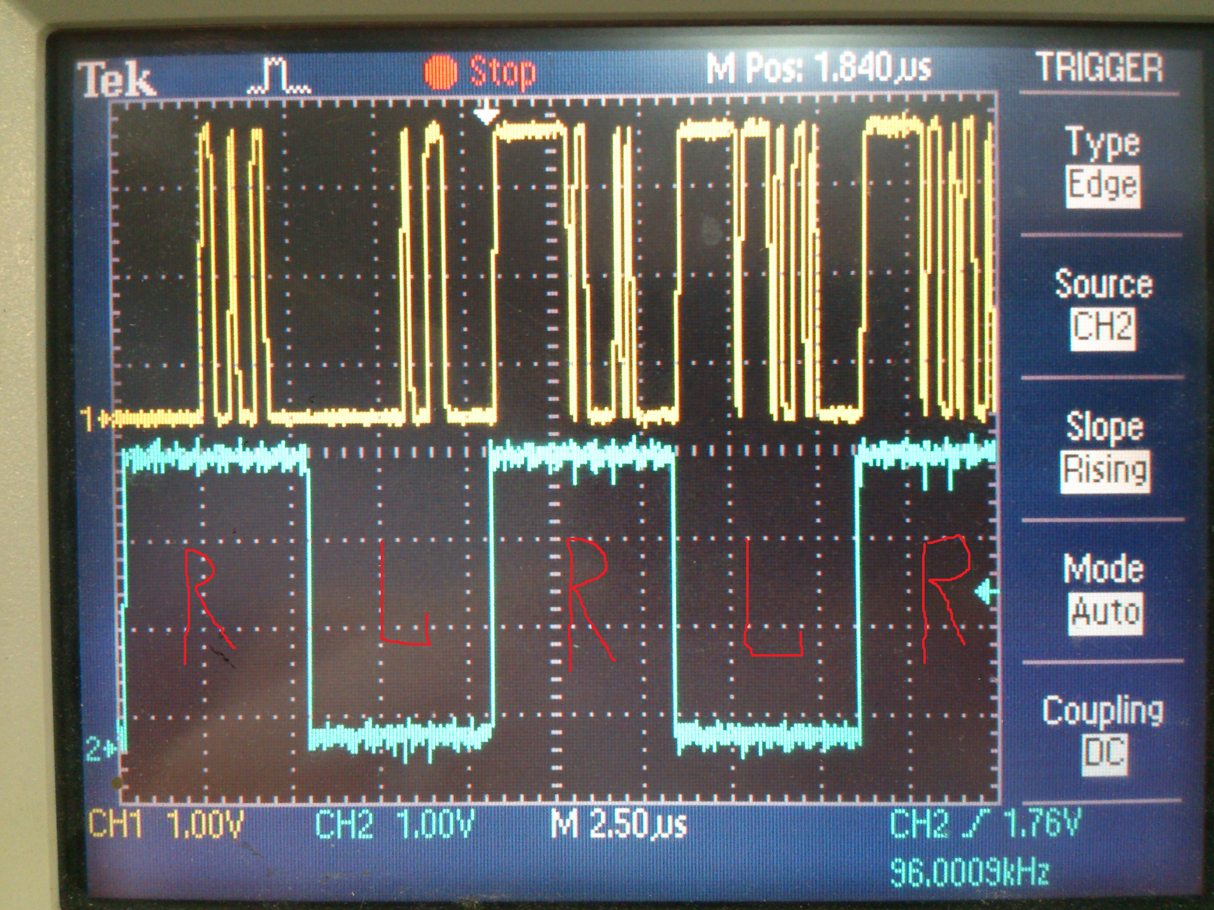
CH1  - DATA Pin

CH2  -  LRCK Pin

Why data from left and right channel are very different ?

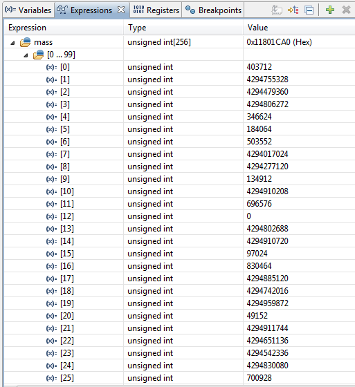
This is confirmed by data from buffer.

This problem hurts me a one week. I've tried  the different chip (PCM4220), check my schematic with datasheet, but I don't have any result. Where is my mistake ? 

Thanks.

  • Hi,

    Our Hardware expert is looking into it and he will get back to you shortly.

    Thanks for your patience.

    Regards,
    Sivaraj K
  • Hello Alex,

    What is the input connected to VINL and VINR of the Audio Codec ? Are these inputs same or different ?

    I believe the master clock for McASP must be same as PCM4220. Why are you using different master clock ?

    I suspect the problem on the codec circuitry or codec configuration issue. I saw you post in audio converter forum regarding the same issue, i hope they would support you better on this regard.

    e2e.ti.com/.../428372

    Regards,
    Senthil
  • Hello SenthilKumar,

    I suggest my problem. On my board Right channel high-pass filter and Left channel high-pass filter - was enabled. I connect DC voltage to VINL and VINR of the Audio Codec but high-pass filter BW = 22Hz to 40kHz.


    I slit paths on the circuit board and pull up (HPFDR & HPFDL) pin. Master clock I connect to 12,288 MHz - > my device work fine.

    But I have some questions.
    When I using Buffer Circuit with Standard Op Amps I have next:

    Buffer input (2,432V DC)
    Buffer output + (2,2085V DC)
    Buffer output - (1,7056V DC)

    ADC code after conversion:
    1011110000100011000000000000 bin

    after discard the least 8 significant bits:
    10111100001000110000 bin = 770608 dec

    I am using the next formula:

    U_input = (5,6 V x 770608)/ 16777216 = 0,257 V

    If
    2,2085V - 1,95V = 0,2585 V
    1,95V - 1,7056V = 0,2444 V

    My calculation is correct ?