This thread has been locked.

If you have a related question, please click the "Ask a related question" button in the top right corner. The newly created question will be automatically linked to this question.

C6713 GPIO Help!!!


Hi!

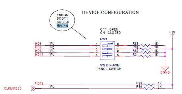
In a project with other classmates we are interfacing a microcontroller with the C6713 through the GPIO ports. The C6713 is on a C6713 DSK by Spectrum Digital. The GPIO is multiplexed with some HPI pins and is disabled by default. I have read in many places over the Internet and in the SPRS294B document that In order to enable the GPIO pins you must connect a pull down resistor in the HD14 pin at reset so the HPI can be disabled and the GPIO enabled.

I have looked in many forums and web pages how to do this but I haven't been able to do it right. I found that the HD14 pin is multiplexed with the GP0[14] pin and on the DSK Board, it is connected to pin 25 of the J1 HPI Expansion connector. I have already connected this pin to one of the board's system ground pins with a 10K resistor. I disconnected the board from power and connected it again, pushed several times the "reset" button that it has, combined these two actions with the closing and re-opening of CCS and I haven't been able to make the GPIO work!!

I can only write on GPIO pin 2. But the other pins seem to be doing nothing but staying in a High or Low level which indicates that they are not enabled as GPIO but as HPI.

I would really appreciate if someone could tell me how can I exactly disable the HPI and enable the GPIO. Which pin is the one I must connect to ground, the resistor value and how to make this work. I don't know what does this mean:

"To enable the McASP1 peripheral pins
and the eleven GPIO pins, an external
pulldown resistor must be provided on
reset."

Here is my C code, and I said before, I have been able to write only to GPIO pin 2.


#include <dsk6713.h>
#include <csl_gpio.h>
#include <csl_gpiohal.h>
#include <csl_irq.h>


GPIO_Handle gpio_handle;  /* handle para el GPIO */

//Configuración de los registros del GPIO

GPIO_Config gpio_config = {         

    0x00000000, // gpgc = Modo Passthrough de Interrupciones y control directo sobre GP0

    0x0000FFFF, // gpen = Todos los pines de GPIO de 0 a 15 habilitados

    0x00000000, // gdir = Todos los pines de GPIO como entradas

    0x00000000, // gpval = Guarda el nivel lógico de los pines

    0x00000000, // gphm all interrupts disabled for io pins

    0x00000000, // gplm all interrupts to cpu or edma disabled

    0x00000000  // gppol -- default state */

};


void main() {

    DSK6713_init();   

    gpio_handle = GPIO_open( GPIO_DEV0, GPIO_OPEN_RESET );

    GPIO_config(gpio_handle,&gpio_config);


    GPIO_pinDirection(gpio_handle , GPIO_PIN0, GPIO_OUTPUT);
    GPIO_pinDirection(gpio_handle , GPIO_PIN1, GPIO_OUTPUT);
    GPIO_pinDirection(gpio_handle , GPIO_PIN2, GPIO_OUTPUT);


    GPIO_pinWrite(gpio_handle,GPIO_PIN0,1);
    GPIO_pinWrite(gpio_handle,GPIO_PIN1,1);
    GPIO_pinWrite(gpio_handle,GPIO_PIN2,1);
}


Thank you very much for your help.


Jorge Cifuentes

  • There's a switch made for this purpose -- here's a screenshot:

  • Thank you Brad! I finally got the GPIO working.


    But now I got a problem. While working with the DSK it suddenly lost connection with CCS. This has happened before to me so it is not a great issue: I just unplug and plug again the DSK and load again CCS. So I did this but I left the 4th Switch of SW3 on the Board up.  When the DSK was on again, it didn't run the POST program where the four leds blink and a signal is sent to the audio codec.


    I didn't know that this switches do some configuration for the DSP when it is turned on. So when I tried to load again my program, CCS told me that the endianness was not right... This was very strange.... So I closed CCS and unplug and replug the DSK again. This time CCS didn't connect to the DSK.


    I reseted the DSK with the RESET button but still the same. I put down the switch in SW3 and did the reset again. Unplug and plug again the DSK with all the switches off but still the same: the POST is not running and CCS can't connect to the board.

    A teacher told me that those swithces determine some kind of configuration on the DSK so I must have unconfigured the board without knowing it. If I run the DSK diagnostics tool, the "DSP test" fails.


    I would like to know if what happened to the DSK can be fixed or if there is someway to reset it to factory settings.


    Thank you very much


    Jorge Cifuentes

  • Hi Jorge,

    The SW3 dips are supplied from the factory set to "off:off:off:off" (factory settings), and this is suggested as the default settings in the Technical Reference manual that ships with the board.

    Set the dips to "off:off:off:on" if you want to use the GPIO lines.

    They are multiplexed and when you set the dip to ON, the HPI lines are disabled and the GPIO lines are made available at the J connector.


    Remember also to short the DC_DET pin to GND to enable the EMIF to be available at the J connectors if you need those.


    Good luck...I had a similar problem where I couldnt get my GPIO lines to output anymore, and this fixed it.

    However I dont know if this relationship between Dip4 of SW3 and the GPIO lines is documented anywhere ?

    If someone knows could they please point it out.

    Thanks,

    C.

  • Hi C.

    This relation of Dip4 of SW3 and GPIO is not documented directly. It is more like putting together the two pieces of the puzzle:


    The document SPRS294B of TI that is like the datasheet of the C6713 points out several times that 11 GPIO lines [15:8, 3, 1, 0] are internally muxed with HPI lines and are not active by default. It says that in order to enable these lines, the HPI_EN (HD14 pin) must read a '0', otherwise, the HPI lines are active and those GPIO lines are off. (page 34)

    Later, quoting the explanation in the datasheet (at page 39), it says:

    "By default, the HPI peripheral pins are enabled at reset. McASP1 peripheral pins and eleven GPIO pins are disabled.
    To enable the McASP1 peripheral pins and the eleven GPIO pins, an external pulldown resistor must be provided on the HD14 pin setting HPI_EN = 0 at reset."

    I guess this is easy to do if you have the DSP alone without an evaluation board. But if your DSP is in an Evaluation Board, specially in a Spectrum Digital DSK, they don't tell you directly that there is a switch on the board to make this connection with the pulldown resistor. You can only know this if you read very carefully the Reference Technical Manual provided with the board. But the drawing is soooo small and is at the last pages of the manual that it is very easy to not seeing it.

    Right know I am having a problem with my board which I already posted in another thread so I can't continue working with my program. But when it worked, I remembered that the GPIO pins 8 to 15 didn't read high values, they only sent me 0's, even though i connected them to +5V my program kept reading a '0' from them.

    When working with the GPIO pins which are not multiplexed, (pins 2, 4, 5, 6 and 7) I didn't have this issue. Do you know what may have caused the rest of the GPIO pins to read only low values?


    Thanks!


    Jorge Cifuentes


  • Jorge Cifuentes said:
    But when it worked, I remembered that the GPIO pins 8 to 15 didn't read high values, they only sent me 0's, even though i connected them to +5V my program kept reading a '0' from them.

    The 6713 is a 3.3V device so connecting 5V to it probably damaged it.

  • Hi Brad!


    Then these GPIO pins  work only with 3.3 V??


    I rememebered that I connected also the GPIO pins [2, 4,5,6 and 7] directly to +5V and GND and everything worked okay. If I had damaged the Board, then it wouldn't have functioned the next day right?? Or maybe it has some "tolerance" and after applying to many times 5V it damages?? I am asking this because it was until the next day when everything happened. My first tests worked correctly, but after a while the board "disconnected from CCS.The difference is that the next day I was working with the GPIO pins 8 - 15.

    So, ALL the GPIO pins work with 3.3 V and GND??? Or only GPIO 2,4,5,6 and 7 work with 5 V and the rest with 3.3 V?

    Also, is there a special way to interface with the GPIO (some pull down resistors, pull up resistors) or can I just connect a cable with 3.3 V and GND?

    We are interfacing the board with a microcontroller that works with 5 V. Do we only have to place a resistor in the connection in order to provide 3.3 V to the GPIO?

    In which TI document can I see all these information?

    I also posted another thread with this issue but there I mentioned that there was a USB connection lost with CCS and after that, CCS and Flashburn keep telling that the board does not have the right endianness. Is this a symptom that the DSP is damaged?? Running the DSK diagnostics tool the "DSP diagnostics" test fails.

    I would really appreciate your help Brad. The University they is going to lend me another DSK but I don't want this to happen again to me. I want to be sure that it was the use of +5V with the GPIO pins and not the USB connection lost with CCS what did that to the board. My program printed to CCS stdout the values of the pins with each interrupt so my theory was that the sudden cutoff of the USB communication while sending data to the PC caused this strange behavior to the board.


    Thank you very much


    Jorge Cifuentes


  • "....Then these GPIO pins  work only with 3.3 V??"

    >>Yes, see p99 of the datasheet sprs294b.pdf. It states an absolute maximum input of 4.5V.


    "...does not have the right endianness."

    >>have you got the DIP SW3 set to off:off:off:on...I believe this affects endianness.


    To test your GPIO lines with 3.3V, why dont you simply run your GPIO reading program and connect a wire from 3.3V (from a J* connector pin) to the GPIO input you are testing and see if it changes to a high.? This is simple and safe for your board.

    Once youve proven your GPIO is still OK, you could perhaps interface your 5V micro's digital signals to it via simple HC buffer chip powered from 3.3V. Connect the 5V signal to the buffer through a 10k resistor (for its protection) and then connect the 3.3V output to your GPIO. Or some other level translating method.


    If your program wont run, you can manually set up the GPEN, GDIR regs and read the GPVAL register. At least you can prove your hardware is working.

    Good luck,

    C.


  • Hi C.


    I can't test my program because CCS tells me the DSP doesn't have the right endianness so I can't load any programs to it. The endianness is determined by switch 1 of SW3 on the DSK. That switch was all the time off. I only moved switch 4 of SW3 which only connects HD14 (HPI_EN) to ground via a pull down resistor. I did this in order to enable the GPIO lines 0,1,3 and 8-15.


    Do you know if there is a way to reset the board? Because I think that maybe it is still functional even though it doesn't run the POST when powered on and I can't load programs to it, CCS still recognizes the board. Or maybe the board is already useless??


    What do you think?


    Thank you very much for your suggestions on interfacing the micro with the DSP.


    Jorge Cifuentes

  • Please can u xplain a bit, m writing on pin 7 but cntinusly geting high voltage, what shud i do