


Tool/software:
Hello,
I need some questions about TPSM365R3RDNR.
i designed TPSM365R3RDNR circuit as below. and output is 3.3V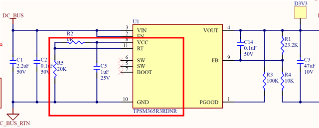
Q1. what is the switching frequency of my TPSM365R3RDNR? because i have connected RT pin with 20kohm to the ground and VCC pin with 0 ohm at the same time(Red box above)
Q2. On your datasheet below, what is the Icc(Bias regulator current limit) parameter exactly means? does it mean output current of internal regulator(for VCC pin) or the output current already consumed by internal circuit?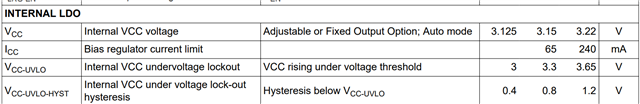
Q3. It is hard to disconnect RT pin and VCC pin for my circuit at this moment, is there any risk connecting RT pin with 20kohm to the ground and VCC pin with 0 ohm at the same time.
so far, me testing, there is no issues yet. that DC/DC circuit output 3.3V well and my 3.3V load works fine..
thank you
