This thread has been locked.

If you have a related question, please click the "Ask a related question" button in the top right corner. The newly created question will be automatically linked to this question.

DP83TG720S-Q1: can not config as slave mode using registers

Part Number: DP83TG720S-Q1

Hi TI,

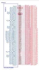
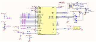
On board we have DP83TG720S-Q1 integrated,and we are using fpga to drive 1000Base-T1 interface.

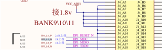
By default, MDI Slave mode is configured by using external pullup 1K resistor on LED_0 pin.I want to configure as slave-mode in normal mode.

I tried just manually to set register 0x834 with 0x8001 value,but it remains the "master" all the time.

To configure slave mode,does any other register need to set?If need to configure other registers,I want to know the minimum register configuration.

  • Hello,

    Are you accessing the registers directly or indirectly? Perhaps this FAQ may be of assistance.

    Sincerely,

    Gerome

  • Hi,

    I access the register 0x0834 indirectly.The following steps were taken but did not take effect and it remains master-mode.

    (1) write 0x000D 0x0001
    (2) write 0x000E 0x0834
    (3) write 0x000D 0x4001
    (4) write 0x000E 0x8000

  • Hello,

    Master mode is configured via bootstraps if LED0 is pulled high. To configure as slave via bootstraps, please use PD on this pin. For register configuration as slave, can you also try utilizing a SW Restart (Reg 0x1F = 0x4000)? Another tell-tale sign of master/slave mode is activity on MDI (assuming the PHY is not connected to its Link Partner); can you corroborate there?

    Sincerely,

    Gerome

  • Hello,

    1. I tried to access the register below.
     Extended mode register: TEST_MODE_CONTROL Register (Address = 0x1904)

     I was able to read and write the results.
     The software extension register using USB2MDIO is set to "no".
     The following is the result.

    Blank reading
     Register 000d is: 0001
     Register 000e is: 0904
     Register 000d is: 4001
     Register 000e is: 0000 ← Check normal_mode (Read operation)
    TEST_mode1 setting
     Register 000D is: 0001
     Register 000E is: 0904
     Register 000D is: 4001
     Register 000E is: 2000 ← Set Test_mode1 (Write operation)
    Check if it is set
     Register 000d is: 0001
     Register 000e is: 0904
     Register 000d is: 4001
     Register 000e is: 2000 ← Confirm that Test_mode1 is set. (Read operation)

    2.I tried to access the register 0x1834 below.

    Blank reading
     (1)Register 000d is: 0001
     (2)Register 000e is: 0834
     (3)Register 000d is: 4001
     (4)Register 000e is: c001  (Read operation)
    Slave_mode setting
     (1)Register 000D is: 0001
     (2)Register 000E is: 0834
     (3)Register 000D is: 4001
     (4)Register 000E is: 8000 ← Set Slave_mode (Write operation)
    Check if it is set
     (1)Register 000d is: 0001
     (2)Register 000e is: 0834
     (3)Register 000d is: 4001
     (4)Register 000e is: c001 ← Confirm that Slave_mode is or not set. (Read operation)

    Why register read is different from write?

    3.I tried above 2 multiple times,but Blank reading(4) results variable,sometimes results is 0000,sometimes is c001.And Check if it is set(4) results variable,sometimes results is 0800,sometimes is 0834,sometimes is c001.

    Does something else should I pay attention to?

    4.I tried to configure SW Restart as 0x4000,but not take effect,it is remaining master_mode.

  • Hi,

    I just tried the reconfiguring a 2x DP83TG720 on their EVM-MC PCB connected via MATEnet and initially linking up (one is master, the other is slave). I configured the master as a slave, and immediate the lights went out and the PHY lost link (as now both are slaves). This was done using the 4 step process of extended access.

    What board are you using? How do you know you are talking to the correct PHY; can you read Reg 0x0, 0x1, 0x2, 0x3? Is this the EVM, or is this own board? If you are using USB2MDIO, how are you connecting to the PHYs MDC/MDIO?

    Sincerely,

    Gerome

  • Hi,

    1.The board is my own board,I connect the PHYs MDC/MDIO through FPGA,The schematic diagram is as follows

    2.I connect the DP83720 to another terminal device1 via MATEnet,and configure the device1 as slave mode.Then power on the DP83720,the DP83720

    can link up and I can read the Reg 0x1 value and its value is 0x0145.Then I configure the device1 as master mode,and immediate the link led went out,

    and I read the Reg 0x1 value and its value is 0x0141.

  • Hello,

    DP83TG720 cannot link up with another device if both are slaves (or both are masters); one has to be master and the other as slave. I think the convention is reversed somewhere along the line. 

    DP83TG720 is a master if Reg 0x1834 = 0xC000, and slave is 0x8000.

    Sincerely,

    Gerome

  • Hello,

    I know it,so I configure another device as master.The DP83TG720 cannot link up when power on(led_0 pullup the default role is master).

    I tried to configure the DP83TG720 as slave but it failed.My steps are as follows

    Slave_mode setting
     (1)Register 000D is: 0001
     (2)Register 000E is: 0834
     (3)Register 000D is: 4001
     (4)Register 000E is: 8000 ← Set Slave_mode (Write operation)

  • Hello,

    Can you try and probe DP83TG720's MDI lines when disconnected from LP? If it is master, it would have the signals, while slaves are silent. This would be able to confirm master and slave commands. You can also use this guidance to also confirm master/slave on device1. We have tested this device for interoperability between other T1 devices, so this is surprising to see that while it as master and LP as slave works, the other way does not. Can they confirm master/slave on each device, as well as if device1 can connect to another device1 and likewise for DP83TG720?

    Sincerely,

    Gerome

  • Hello,

    I'm very sorry for the unclear explanation of the previous issue.

    I am sure the main issue now is the failure to write to the extension register.

    1.I tried to read register 0x0003(PHYID2) to ensure normal reading,read and write register 0x000E(ADDAR) to ensure normal reading and writing

    read Reg 0x0003(PHYID2) and its value is 0xA284  ← Confirm that read operation is ok

    read and write Reg 0x000E

        (1)Register 000E is: 0904 (Write operation)
     (2)Register 000E is: 0904 (Read operation) ← Confirm that read and write operation is ok

    2.I tried to access the register 0x1904(TEST_MODE_CONTROL) below.

    Hardware reset

        (1)Register 001F is: 8000 ← Hardware reset (Write operation)

    Blank reading
     (1)Register 000d is: 0001  (Write operation)
     (2)Register 000e is: 0904  (Write operation)
     (3)Register 000d is: 4001  (Write operation)
     (4)Register 000e is: 0000  (Read operation)

        sometimes the step(4) read Reg 0x000e and its value is 0904(Why the address value appears in the register corresponding to the address?)


    Test_mode 1 setting
     (1)Register 000D is: 0001
     (2)Register 000E is: 0904
     (3)Register 000D is: 4001
     (4)Register 000E is: 2000 ← Set Test_mode 1(Write operation)
    Check if it is set
     (1)Register 000d is: 0001
     (2)Register 000e is: 0904
     (3)Register 000d is: 4001
     (4)Register 000e is: 0000 ← Confirm that Test_mode 1 is or not set. (Read operation)

    I don't know why the extension register configuration doesn't take effect.

    Do I need some other actions to ensure that the extension register configuration is effective?

  • Hello,

    You state you are using USB2MDIO. What is the Microcontroller used for this? We have designed USB2MDIO to be used with MSP430, so anything device other than that may not have proper functionality. Could you try to scope out the MDC/MDIO lines to confirm extended method is taking effect? 

    Sincerely,

    Gerome

  • Hi,

    I didn't use USB2MDIO.I connect the PHYs MDC/MDIO through FPGA,The schematic diagram is as follows

    I use FPGA to drive the SMI interface.

  • Hello,

    Understood. Can you try and scope the lines then to see if the proper commands are coming out and reading back?

    Sincerely,

    Gerome

  • Hello,

    I tried to read register 0x0003(PHYID2) to ensure normal reading,read and write register 0x000E(ADDAR) to ensure normal reading and writing

    read Reg 0x0003(PHYID2) and its value is 0xA284  ← Confirm that read operation is ok

    read and write Reg 0x000E

        (1)Register 000E is: 0904 (Write operation)
     (2)Register 000E is: 0904 (Read operation) ← Confirm that read and write operation is ok

    I can confirm that reading and writing are normal through the above steps.

  • Hello,

    While I do agree that direct access reading may work, I would like to still double check the indirect method on scope to understand what could possible be going wrong there. 

    Could you also try hardware writing the reset and checking the MDI line to confirm that the behavior is cutting the line momentarily? When you read back this value, it should be 0x0 as it is self clearing. You can also try writing loopbacks on registers 0x16 for a more static test point. The register steps you wrote for indirect access write are the same ones I did for changing master to slave.

    I can double check in lab on my EVM to see Reg 0x1904.

    Is this issue happening on the single board or on multiple boards?

    Sincerely,

    Gerome

  • Hello,

    I just checked Reg 0x1904 by writing 0x4000 and I did see a change in the MDI signaling.

    Sincerely,

    Gerome