Hi Experts,
When the input of driver transients from high to low or low to high, there is about 5us idle state on Vod like below.
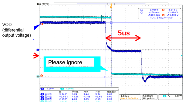
Is it expected behavior?
Regards,
Uchikoshi
Hi Experts,
When the input of driver transients from high to low or low to high, there is about 5us idle state on Vod like below.
Is it expected behavior?
Regards,
Uchikoshi