This thread has been locked.

If you have a related question, please click the "Ask a related question" button in the top right corner. The newly created question will be automatically linked to this question.

SN65C3232E: EMI and schematic review

Part Number: SN65C3232E
Other Parts Discussed in Thread: SN65C3232

Hi team,

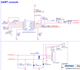
Could you please help my customer to check the schematic of SN65C3232EPWR, and if there is any EMI issue in the circuit. 
I think the schematic of SN65C3232EPWR is good, but I am not sure about the EMI part.
below is the schematic of SN65C3232EPWR, this is for UART.

  • Hi Jason,

    The charge pump capacitances look good at C1=C2=C3=C4=100nF=0.1uF. Appropriate bypass cap at 100nF on VCC to GND is good. The ferrite beads from VCC = 3.3V to the RS232 transceiver will help to filter a noisy supply before it reaches the device. Correct bypass capacitor connected from VCC to GND.

    The SN65C has max signal rate of 1MHz. Since this application is using UART <-> RS232, I would assume the signal rate is quite low. Series ferrite beads on pins 14 and 13 are maybe extra components. Since you are potentially operating at low frequencies, the ferrite beads effectiveness is quite small. 

    My main concern is the TVS diode D158 and diodes D75 and D157. The TVS diode D158 is not quite protecting the bus. If you were to have a bus fault across UART_IN_TX to UART_IN_RX, the TVS diode will be shorted. To change this, there should be two TVS diodes from each bus to GND: UART_IN_TX to TVS to GND and UART_IN_RX to TVS to GND. 

    This idea was maybe thought about when implementing D75 and D157. Looking at the datasheet for P4SMAJ, I believe these diodes D75 and D157 are unipolar. 

    This would not be good for your current application. Given that the SN65C3232 is a RS232 transceiver, you will see RS232 like signals on the driver outputs DOUT. This voltage level can swing typically from 5.5V to -5.4V. If the diodes D75 and D157 are unipolar, when you have a negative voltage output pins 14 and 13, you will see a short circuit from the transceivers RS232 drivers to GND. This could potentially break the transceiver due to short-circuit current draw from the supply. 

    I think everything else is good with the design. Please let me know if you have any more questions. 

    Regards,

    -Tyler

  • Hi Tyler,

    Thanks for your help.

    According to your answer, I have some concerns, I'd like to discuss with you.

    I have a concern about, why you said that adding D75 and D157 could break the transceiver? adding D75 and D157 to avoid minus voltage in receiver. So pins 14 and 13 both will be connect to ground? does this not make sense? Could you tell me how many current will draw from the supply? 

    UART_IN_TX to TVS to GND and UART_IN_RX to TVS to GND.  customer cannot use D75 and D157, also need to remove the D158 right?


    Jason

  • Hi Jason,

    The lines connecting pins 13 and 14 are the input/output RS232 lines to the remote RS232 system. RS232 signals swing from positive voltage to negative voltage, thus the absolute max input voltage range for the RS232 receiver on this device is -25V to +25V.

    In the event of a voltage spike, say 30V, on pin 13 = UART_IN_RX, D157 would reach its reverse breakdown voltage and source this high voltage event to ground before it reaches the transceiver. This is the good scenario, the diode did its job! What I am afraid of is the polarity of diodes D75 and D157 because if you were to reverse the situation, say -30V fault, you now have the bus line at a lower voltage than ground, which would forward bias diode D75. You now have -30V on the receiving lines of the device, which is outside abs. max conditions. 

    The solution would be to replace D75 and D157 with bi-polar direction TVS diodes. Maybe the datasheet for the P4SMAJ says otherwise, but from my quick search it seems that both on the datasheet and the schematic provided, these diodes will only protect for one-half of the RS232 signal. These diodes are unipolar.

    Yes, remove D158, I do not see how this diode is helping to counter a bus fault condition.

    The current draw from the supply will depend on many different factors. General rule, if you operate the inputs/outputs of this device outside abs. max conditions, you may draw more current ICC that would be outside the max conditions in the power section of the datasheet. Max current this device can draw is 1mA, typically 0.3mA. 

    Regards

    -Tyler

  • Hi Tyler,

    I got it.

    Thanks for your explanation.

    Jason