Other Parts Discussed in Thread: TCAN1043A-Q1, TCAN1043-Q1, TCAN1044A-Q1, TCAN1044-Q1, TCAN1043, TCAN334
Hi Expert,
When I use TI CANtransceiver, I have some confusions about TCAN1044AV-Q1 and TCAN1043A-Q1. Hope you can help about these questions.
- How to determine whether to use 5V CAN FD or 3.3V CAN FD if MCU supply voltage is 3.3V? Is there any advantages for 5V CAN FD over 3.3V CAN? In most applications, I have seen that 5V CAN FD is used though MCU supply voltage is 3.3V.
- What is the advantage of TCAN1043A-Q1 over TCAN1044A-Q1? I think one value is that TCAN1043-Q1 has sleep, silent and standby mode while TCAN1044-Q1 only has standby mode, so that TCAN1043-Q1 is more power saving device. Is there any other values for 1043 compared with 1044? In which application will prefer to use TCAN1043?
- In my view, when 1043 works in sleep mode, all system components like MCU will not be powered except 1043. I am not sure whether it is correct. However, in the mandarin version of the datasheet, the description of the device is that in sleep mode of 1043, power will be delivered to all components except 1043. I think these two descriptions are opposite to each other.
- For the WUP of 1044, once the bus recognize the WUP, the RXD output is driven low. I think this time the node will return to normal mode. After it returns to normal node, why will it still need to wait for twk_filter so that the RXD output can be driven low?
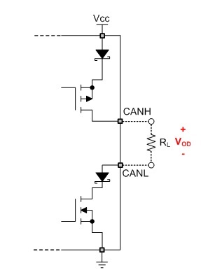
- Why CANH is 3.5V and CANL is 1.5V when bus state is dominant? I am not sure about the relationship about 2V differential voltage with Vcc(5V). Will it be related with the termination resistor? Is there any formula or explanation about this relation?
Thank you very much for your kind help and looking forward to your reply!