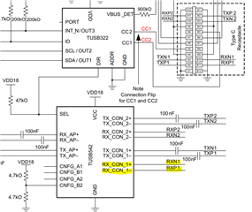
Hello team,
I think the highlighted parts are mixed up, is the datasheet correct?

Regards,
Masakazu
This thread has been locked.
If you have a related question, please click the "Ask a related question" button in the top right corner. The newly created question will be automatically linked to this question.
Hello team,
I think the highlighted parts are mixed up, is the datasheet correct?

Regards,
Masakazu
Masakazu-san
The pin name in the EVM needs to be updated.
RX_AP+/- (pin 17 and 18) is the output, which needs to be AC coupled (C1 and C2).
TX_AP+/- (pin 14 and 15) is the input, since the AC coupling caps are on the corresponding TX, then there is no need for AC coupling caps. Please note that in the latest USB ECN, they do recommend optional 330uF cap on TX_AP+/- on the receiver side.
Thanks
David
Hello David-san,
I'm asking a different question.
I think the positive and negative connections in the highlighted area are reversed in the datasheet and EVM.
Is either correct?

Regards,
Masakazu
Masakazu-san
There is no issue with swap polarity, for USB3 specification all the USB3 PHYs must be able to detect any polarity inversion and compensate it.
Thanks
David