This thread has been locked.

If you have a related question, please click the "Ask a related question" button in the top right corner. The newly created question will be automatically linked to this question.

TCA6424: Design review

Part Number: TCA6424

Hi Team,

Our customer design uses the TCA6424A. Due to delivery problems, they decided to use TCA6424 as an alternative based on the Errata of the datasheet.

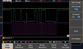
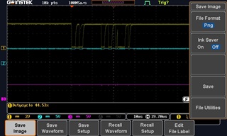
However, they observed that the interrupt does not behave as with the previous chip. It instantly ge de-asserted (see attached picture).

- Reading from register 00h is never our last command. We always read register 00h, 01h and 02h after each other in this order.

- We have no other I2C slave connected (only the STM32 as master)

The interrupt is only very shortly active around 1us and gets immediately de-asserted. That you see several activations of it comes from a bouncing switch as they have an RC filter on the electronic (interrupt line) these short pulses gets filtered.

According to the customer, The behavior which they observe is not related to the Errata and they suspect that the chip has more differences to the TCA6424A than listed in the Errata.

Here is the schematic for additional information:

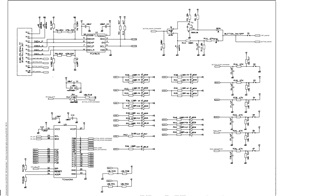
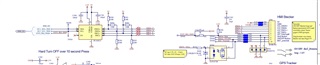
The TCA6424 replaces U3 on the HMI (separate PCB) and is connected by wire to the Baseboard. On the baseboard is a STM32 (the other side of the I2C). For better signal quality over wire, they implemented PCA9615 on both sides. 

Can you help the customer to handle the chip same the same as the TCA6424A?

Regards,

Marvin

  • Hi Marivin,

    I believe that the errata on this device is that any time you read the register 0x00 the INT pin can be improperly de-asserted. When they say

    "This generally means the last operation with the device was a Read of the input register. However, the command byte may have been written with 00h without ever going on to read the input register. After reading from the device, if no other command byte written, it will remain 00h."

    It does not mean that the errata will only happen when the register 0x00 is read last, this means that even if you preform a write of 0x00 to a register and that is the last write you preform then the errata can also occur. If possible can you provide a scope shot of the INT pin and SDA and SCL signal lines I would like to see what command desserts the INT pin.

    Best,

    Chris

  • Hi Chris and Marvin

    We have performed hopefully the wished measurements. Maybe Marvin can upload the images to this case.

    The 2 measurements show (yellow=Interrupt, blue=SDA, purple=SCL):

    1. A I2C communication (initiated by STM32 side, no interrupt involved)

    2. A interrupt due to a buttom press (with bouncing) on the TCA6424. Which will not be detected by STM32

    We have checked and addapted the FW for a test, so that we never send 0x00 as address nor as data. But this did not change the behavior.

    In the meantime we have found a strange passage in the datasheet:

    "In the TCA6424, an interrupt is not immediately generated by any rising or falling edge of port inputs in input mode after issuing any I 2C commands (read or write). In order to capture the INT in the TCA6424, the user needs to add one more SCL clock pulse after a Stop signal."

    We have not implemented this additional clock pulse. It is not required for TCA6424A. It is even not defined in a standard I2C communication. It sounds like a hack to me.

    Could this be the root cause for our behaviour?

    Why is this not mentioned in the Errata section, sounds obviously as an Errata to me?

    Is there any setting known for STM32 IC2 driver which would fix this? We want to have a clean solution for that, not a hack.

    Does the TCA6424A work as well with this additional clock pulse?

    Does this clock pulse influance/disturb other I2C devices as we have to add this to I2C driver?

    Thanks for your support

    Roman

  • Hi Chris and Roman,

    Here are the pictures mentioned above:


    I hope this helps.

    Regards,

    Marvin

  • Hi All,

    I will read through this and get back to you tomorrow.

    Best,

    Chris

  • Sorry for the delay on this guys,

    Can you show a scope shot of the INT pin when an input port changes? The INT pin will only change when an input port changes value from it's stored state. So on a scope shot can you show yourself toggling an input port and see if the INT gets set.

    For the second scopeshot I'm a little confused. Are you pulling the INT low by your self and the MCU is not reading it? this would not be an issue of the TCA6424 and rather an issue with your MCU.

    This extra clock cycle that you bring up is part of the Interrupt errata for this device. The TCA6424A does not require this but it will work with an extra clock cycle. To be extra careful, all I2C devices are designed so that if you send 9 clock cycles the SMBus registers are reset. This will allow you to communicate normally incase there is a hangup on your bus.

    This extra clock cycle is only required if your input port changes value while the device is issuing an I2C command, if there is no I2C communication the INT should trigger immediately after an input port has it's value changed. Even if you don't have the extra clock cycle the INT should eventually trigger after an I2C command once it reads the input ports it just won't be immediate. This is all part of the errata and is not expected behavior for this device so there is no timing defined for this case.

    Once there is more availability for the TCA6426A I highly recommend transitioning over to that device. It is drop in compatible.

    Best,

    Chris

  • Dear Chris

    Just for clarification. We have our device perferctly running with the TCA6424A so far.

    But due to delivery problems we are forced to produce a batch with the TCA6424, which we could organize over a broker. We had not other choice.

    Strange thing:

    The TCA6424 runs now as we would have expected. The interrupt is correctly pulled low and stays low as long the pin is changed.

    The input is filtered by RC element and does not show any bouncing. Rise time 80ms, fall time 80ms. Sorry, I struggle to upload a plot of it to taht forum.

    But I do not understand why the Interrupt is correct now:

    In the meantime we have ensured that no 00 will be written either as address or data as last communication. But we have tried this FW change without impact on the Int.

    Before I have measured the correct behavior, I have soldered a wire to the PCB to 1 input pin. But before all input pins resulted with the same failed interrupt behavior.

    It does not make sense to me that the failed interrupt shows a bouncing in us, while the input signal raises constantly without bouncing.

    It looks like our problem is solved.

    The bad thing is, we dont know why. And we do not know why we had intially problems with the TCA6424.

    If you have an idea. You are welcome to share it. I would feel more confident that the next produced batch works as it sould.

    Best regards

    Roman

  • Roman,

    It would be interesting to see what the pin input looks like when the INT is bouncing. I've been talking to design about this issue and these interrupts can be de-asserted when the input pin that caused the interrupt goes back to it's original value without ever reading the input register. It is possible that there is some noise on the input pin that could cause the interrupt to assert and de-assert.

    I was also thinking about the extra clock cycle requirement in this device. This device is a very old design but in order to satisfy the extra clock requirement and to keep all of your I2C writes constant you could just send an immediate write to a fake device address. What will happen is the MCU will see a NACK and it can continue communicating without you having to code in an extra clock cycle. This way the extra clock cycle requirement is satisfied. Apparently with this device it is possible that without the extra clock cycle the INT gets stuck low and it never de-asserts. So after every write to this device you would have to immediately send a fake write to another device so that there is always an extra clock cycle.

    I am going to see if I can get my hands on this device so I can test it in the lab to verify that this would be an appropriate solution. Luckily if this is a fix then you should be able to swap back in the TCA6424A without having to change the software.

    Best,

    Chris

  • Dear Chris

    As a RC filter (see schematic) is designed to the input pin, it is not realistic to have noice on the input pin (especially bouncing). The problem is that we can not reproduce the initial faulty behavior since Wednesday when the chip work as we would expect (no longer deasserting of the Interrupt).

    It could be a bad soldering (e.g. bad solder C of the RC element) which has been fixed somehow by manipulating the PCB. Even though it does not make much sense, as the behavior was observed on several input pins. However we soon get the produced batch with the TCA6424 and will test it to see if we have the same behavior.

    Other thing is maybe that your FW changes fixed it even though we have not seen it during the development of the changes. We will retest that with an old FW version to see if we have the deasserting of the Interrupt again.

    Best regards

    Roman

  • Ok Roman,

    Well keep me updated. I did ask my team if we had any non-A devices that I could test in the lab but we do not have stock of that device. Without being able to recreate the problem it will be hard to debug exactly what the issue was.

    Best,

    Chris