This thread has been locked.

If you have a related question, please click the "Ask a related question" button in the top right corner. The newly created question will be automatically linked to this question.

DS250DF230: Does the retimer adaption time is fixed during multiple bring up?

Part Number: DS250DF230
Other Parts Discussed in Thread: LMK04828,

Hi Team, 

I have some questions about retimer. Could you please help me on that? 

1. I have two SFP28 SIP optical ports on the boards and the trace between SIP and ASIC are difference between them, one is much longer than another and I need to use 25G retimer to compensate the IL. I am concern about the lane delay introduced by the retimer will make two SIP to ASIC lane delay different during multiple start up. Because I suppose that the CTLE and DFE adaption time is random, am I right? If yes, how could we manager this issue? 

2. Does the CDR in the retimer is simlar as a PLL? The input is the raw data and the output is the pure clock which from integrate VCO. If the error between input data frequency and output frequency with a configurable certain range and exceed the PPM counter threshold, the CDR will lock.

3. If it is yes, why we add an external clock to run the PPM counter? I saw other TI device such as LMK04828 it didn't have the requirement for an external oscillator. 

4. How to choose a FIR filter main, pre, post cursor value when given eye height and channel IL loss?  I look through the DS250DF230 datasheet, how to interpret this figure with the FIR table? 


Thanks. 

B.R.

Zhizhao

  • 1. I have two SFP28 SIP optical ports on the boards and the trace between SIP and ASIC are difference between them, one is much longer than another and I need to use 25G retimer to compensate the IL. I am concern about the lane delay introduced by the retimer will make two SIP to ASIC lane delay different during multiple start up. Because I suppose that the CTLE and DFE adaption time is random, am I right? If yes, how could we manager this issue? 

    • If it is important for your system that two retimer channels have similar adaption time you may try manually setting the CTLE boost.
      • For retimer input channel of insertion loss less than 7dB you may set CTLE to its lowest boost value, CTLE = 0x00
      • For the longer channel you may perform a test where CTLE is allowed to be adapted automatically. You can then read the adapted CTLE value observed via channel register 0x8F and subsequently force this CTLE boost setting
      • The channel register write operations for manually forcing CTLE are included below. I would recommend to use adapt mode 2 with DFE enabled to allow for optimal retimer input eye opening margin

    Table. Set CTLE Boost Value


    STEP

    SHARED/ CHANNEL REGISTER SET

    OPERATION

    REGISTER ADDRESS [HEX]

    REGISTER VALUE [HEX]

    WRITE MASK [HEX]

    COMMENT

    1

    Channel

    Write

    2D

    08

    08

    Enable CTLE boost override

    2

    Channel

    Write

    03

    xx

    FF

    Set CTLE boost to desired value. Different input channel loss will require different CTLE settings.

    2. Does the CDR in the retimer is simlar as a PLL? The input is the raw data and the output is the pure clock which from integrate VCO. If the error between input data frequency and output frequency with a configurable certain range and exceed the PPM counter threshold, the CDR will lock.

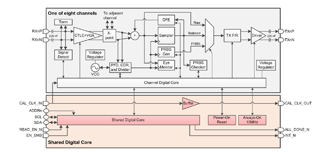
    • The retimer CDR shares functional blocks with a PLL system and behaves similarly but a pure PLL and a retimer IC are not equivalent. See below retimer functional block diagram from TI datasheet
    • Indeed there is a PPM check function implemented by the retimer. The CDR is not allowed to lock if frequency delta exceeds a defined PPM threshold

    3. If it is yes, why we add an external clock to run the PPM counter? I saw other TI device such as LMK04828 it didn't have the requirement for an external oscillator. 

    • The retimer digital logic requires the 25MHz calibration clock to serve as reference for calculating the frequency PPM. Most likely the LMK device you are looking at is a pure PLL and not a CDR retimer with PPM check function

    4. How to choose a FIR filter main, pre, post cursor value when given eye height and channel IL loss?  I look through the DS250DF230 datasheet, how to interpret this figure with the FIR table? 

    • If we use as example the 15dB insertion loss plot that you included in your plot, you will see there is a blue region of FIR pre-cursor/post-cursor value combinations. This is the region where TI empirically observed good link BER performance. In the plot there is de-emphasis value listed in dB for both pre-cursor and post-cursor. You would want to set your Tx to settings yielding these de-emphasis values
    • Though the FIR plots in TI's datasheet serve as an initial guideline, TI would recommend that you perform your own system level sweep of Tx FIR pre-cursor vs post-cursor to determine what settings yield optimal Rx BER and input eye opening. You may refer to the TI white paper below for more information on Tx FIR sweeps.

    Thanks,

    Rodrigo Natal

    HSSC Applications Engineer