This thread has been locked.

If you have a related question, please click the "Ask a related question" button in the top right corner. The newly created question will be automatically linked to this question.

TL28L92: TL28L92 Multi-drop (9-bit) mode difference compared to NXP SC28L92

Part Number: TL28L92

We've used the TL28L92 to replace an obsolete NXP SC28L92 and found it works fine in 8-bit mode but does work in Multi-drop (9-bit) mode.

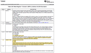
In Muti-drop (9-bit) mode the PARITY TYPE bit in Mode Register 1 determines the state of the 9th bit, the A/D bit, when a byte is transmitted. The state of the PARITY TYPE bit is supposed to be captured when a byte is written to the TX FIFO so that each byte is eventually transmitted with the previously captured 9th bit. It appears that the TL28L92 is not capturing the PARITY TYPE state and is instead using the current state of the PARITY TYPE bit while transmitting each byte.

  • does NOT work in Multi-drop (9-bit) mode. That is ...

  • We've also confirmed that an Exar/MaxLinear XR88C192 also functions correctly on our board in 9-bit mode.

  • David,

    An engineer has been notified of this post and will respond by Monday 11/7/2022.

    Regards,

    Eric Hackett

  • Hi David,

    To be honest, I'm not very familiar with this kind of UART mode (seems we don't have many UART devices with this kind of mode). Is the first byte supposed to have the 9th bit set as 1 to indicate it's an address, the second supposed to be set to 0 to indicate it's data and stay that way until the next address byte is sent? 

    I can try to reach out to our design team to see if they can verify how this mode is set up in the design files however there is a chance that the design files might not be able to be located as this device is quite old. This may end up being a bug that wasn't found in the device back when it was created. 

    -Bobby

    Edit: I reached out to the design team, I will let you know when they get back to me. It may take a couple days.

  • Bobby,

    In 9-bit mode the state of bit 2 below (page 32 of datasheet) is supposed to be captured when each byte is written to the TX FIFO. 1 and 0 indicate address and data,respectively. When each byte is transmitted the previously captured state of bit 2 is supposed to be transmitted as the 9th bit. It appears that bit 2 is not being captured and the present state of bit 2 is being transmitted instead.

    Dave Brent

  • Hey David,

    Good news and bad news.

    We were somehow able to locate the design files for the device (I was really pessimistic about the chances of finding it).

    The bad news is the design engineer seems to have found that the designers for this part only made the multi-drop function for receiving data and the multi-drop setting does not affect the transmission. This seems like the original team who designed the device didn't catch this bug. A potential work around for transmission may be to set the register with force parity to make the device output 1 for address followed by 0 for data.

    Sorry, I know this wasn't something you were hoping to hear...

    -Bobby

  • Bobby,

    We tried the workaround you suggested and it doesn't work. Or current options are to use the Exar/MaxLinear XR88C192 or integrate a DUART IP core.

    Dave

  • Hi David,

    Sorry to hear that. Unfortunately I don't think there are any other workarounds and this is the only UART device I'm aware of with this 9 bit multi-drop mode.

    -Bobby