This thread has been locked.

If you have a related question, please click the "Ask a related question" button in the top right corner. The newly created question will be automatically linked to this question.

THVD1520: Best way to protect RS485 chip from ESD, surge and reverse polarity

Part Number: THVD1520
Other Parts Discussed in Thread: THVD1505, STRIKE

Hi,

I was wondering if there were any design guides, pcb examples or references for the best method to protect an RS485 chip from ESD, surge and reverse polarity. 

We are using a molex 4 pin header (0022232041), which doesn't have a casing, so I want to protect the chip as much as possible. 

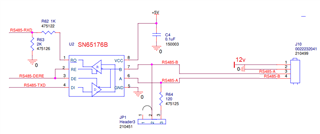
Below is a picture of the schematic,

/resized-image/__size/320x240/__key/communityserver-discussions-components-files/138/pastedimage1675135668111v1.png

  • Hi Andrew,

    So in general the standard approach to protecting an RS-485/RS-422 type bus has a few considerations.

    1. What level of ESD protection is needed in the system? This part is rated +/-8kV for IEC ESD protection and also +/-4kV for EFT  - so it is common for these parts to be used without additional ESD diodes - but that is going to be a system by system level - please see our series of articles on ESD and selecting an ESD diode if it is necessary for the application: https://e2e.ti.com/blogs_/b/powerhouse/posts/esd-fundamentals-part-2-iec-61000-4-2-rating#:~:text=For%20most%20applications%2C%20level%204,voltage%20ratings%20(Table%202). In general a level "4" protection will protect the device in most applications - this would be our devices with a +/-15kV rating or higher (14 half duplex parts are listed here: https://www.ti.com/interface/rs-485-rs-422/products.html#p1065=Half&p1634=15;16;18;30 and these devices generally do not need external ESD protection) 

    2. For surge protection - usually this is handled via a surge diode or by using an RS-485 device with an integrated surge diode (surge protected devices). https://www.ti.com/interface/rs-485-rs-422/products.html#p976max=10;50&p2192=Surge%20protection (surge protected half duplex devices with data rates at 10Mbps or above (the other options are slower at 250kbps). A great resource on how the node should be designed in shown in the THVD1520 with a breakdown on surge/EFT/ESD for these types of applications - it is section 9.1.2.5 starting on page 15. 

    3. Reverse polarity is a bit trickier as it depends on how that is defined.

    The device is fault protected from -18V to 18V so a short to battery (+/-12V) won't immediately damage the device (if the driver is driving during the short event a large current draw is possible which could heat the part quickly and potentially damage the junction. - If the 12V from the connector is being fed into a power circuit that is stepping down the voltage for the THVD1520 then there is very little risk as the device will be high impedance on the receiver so a connection to -12V or 12V is not going to hurt the device when applied to bus pins.

    However if you are talking about swapping the B and A pin - it's a bit tricky - we have a few devices that have polarity correction - https://www.ti.com/interface/rs-485-rs-422/products.html#p2192=Auto%20polarity but I don't think they are good matches for this specific application due to differences between chosen part and the ones we have on offer. But that being said - there is a way to do autopolarity correction - through the controller and using passive failsafe resistors - app note here: https://www.ti.com/lit/an/slyt324/slyt324.pdf - essentially you set up an idle voltage of ~200mV with Host node having the passive failsafe network  - all of the peripheral nodes will then start in "RX" mode and if they are detecting a "1" then the controller at the peripheral node can be programmed to "know" that it was wired correctly where if it is wired incorrectly the input differential voltage will be read as -200mV making the "R" pin output 0V and the controller for that node can be programmed to "know" that it needs to invert the DataStream due to miswiring. This is essentially how the THVD1505 works -(in the part list on above link) without the need to do it via controllers - but it is rated to be much slower than the THVD1520 so it may not work for the application . 

    Please let me know if you have any other questions and I will see what I can do!

    Best,

    Parker Dodson

  • Would adding resistors and a diode in series, between the header and the rs485 IC also add protection? Is this a common method or should the protection the chip has be fine?

  • HI Andrew,

    I don't think a diode in series will offer additional protection and it could hinder communication on the line. A series resistor and a protection diode to ground could add protection to the IC - the tradeoff is that series resistors will attenuate the incoming signal which could shorten max effective bus length. Having a protection diode right of the connector is not uncommon for protection - but its always best each node is individually protected. 

    As for is the protection sufficient  that depends on 2 main factors:

    1. Is +/-18V enough margin for the application in the application? Or are there cases where a voltage could exceed +/-18V?  If yes - additional protection is needed.

    2. How likely in the system is a driver going be actively driving the bus during a battery to short condition (I.e. DE is driven high during short) ? If this chance is low - which I think is a pretty fair assumption, but you know the nuance of the system better than me so you can determine how likely this event is - as while a short duration short wouldn't be a large issue - there could be a large current drawn from the ports which could in turn overheat the junction - so there may need to be additional consideration if this is a risk in the system. If this risk is low than there really isn't more protection needed (unless additional protection is needed due to point 1) 

    Please let me know if you have any other questions!

    Best,

    Parker Dodson

  • Hi Parker,
    1. Think it would have been. We are currently using SP485EEN-L/TR from max linear. It has: ±15kV Human Body Model ±15kV, IEC61000-4-2 Air Discharge ±8kV, IEC61000-4-2 Contact Discharge. We are experiencing nearly 10% failure rate of these chips. 
    I suspect most of the failure is happening when placing our connector on to the 4 pin header we are using. I was sitting in a chair and while I was holding the header, if I were to stand up, it would arc across my fingers. Of course in the shop we are typically not sitting when connecting the headers to the pin but it was easy to replicate the problem. 
    2. The system is always turned off when using the connectors. 
    See the attached for picture reference: https://imgur.com/a/vkl0aZJ

  • Hi Andrew,

    Additional protection may be needed. I understand that there was a static discharge when you were trouble shooting In the office - however what is the assembly/test environment in the shop look like? Are there ESD controls in place? Even with integrated protection some ESD spikes can still be damaging. I am assuming that the shop is probably better suited for the assembly/connection but this is a potential problem.

    I would add an additional ESD diode that could help bulk up the protection - there is a great article series on looking at higher IEC ratings and why additional protection diodes could be beneficial in systems such as yours. since there is failures with the current device I do believe this may be the direction you should look at with respect to ESD protection. The series is here - https://e2e.ti.com/tags/ESD%2bFundamentals%2bseries - it gives a more in-depth explanation on protection levels and what else may be needed. I would look to something that may be higher than the 15kV - as some systems do require more protection. We don't have a specific ESD diode to recommend as in many applications the integrated is sufficient - but this application may require something a bit more robust - so if you want some more information on good fits for ESD diodes our ESD/protection experts here: https://e2e.ti.com/support/interface-group/  and you should get routed to an ESD expert. 

    I do think based on the information you have shared it is a static discharge event that could be leading to failure - adding an ESD diode can help protect - assuming there are sufficient ESD controls for the environment that this is being assembled/connected in.

    Please let me know if you have any other questions - but based on everything shared I do think an ESD diode added externally would be a good idea to help shunt any additional static discharge events.

    Best,

    Parker Dodson

  • Our shop does not have much in the way of ESD protection. I purchased ESD bracelets and those certainly helped but I want to get the product rugged enough so we do not need to be as carful. A lot of work is done in the field and having something any one can work on is preferred. 

    I have looked into TVS diodes. My one question and probably misunderstanding is if the TVS diode gets affected by the ESD, does the board still work or does the TVS diode need to be replaced? If I have to replace the TVS diode, whats the point of it? 

  • Hi Andrew,

    That makes sense from the reliability point of view.

    Adding a higher rated TVS/ESD diode in front of the device should take most of the energy - granting node protection up to the diodes protection levels - as it will be handling the higher energy shock. Ideally the additional diode goes beyond the protection of the device so that nothing is damaged and you aren't replacing anything. The discharge even will be shunted by an external diode. The internal integrated protection gives of the transceiver gives more flexibility in terms of what diode can be chosen as there is additional protection. 

    So in short the diode should be rated higher than the IC its protecting to add benefit to the system. If the discharge is damaging the diode a larger diode may be needed. Adding small pulse proof resistors (~10 Ohms) between the terminals and the protection can also add mitigate issues of fast transient events (such as an ESD discharge). 

    Please let me know if you have any additional questions or further clarification of anything please let me know!

    Best,

    Parker Dodson

  • Okay that makes sense. 

    So adding resistors could be beneficial in helping reduce ESD? Would you recommend a maximum of 10 ohms?

    Thanks for all your help. 

  • Hi Andrew,

    The Series resistors can reduce the peak ESD voltage/current taking some of the brunt of the strike compared to integrated ESD / external ESD diodes alone. 

    It depends on application - generally 10 Ohms to 100 Ohms is what I have seen - but since the system is terminated smaller is better as 100 Ohm series resistors with the termination could effectively cut the max bus length to ~1/3 of its original max length. The trade off is higher resistance will give more protection, but will decrease max distance of bus - as the voltage across the termination resistor will be reduced due to essentially adding a voltage divider to the circuit. It really depends on the attenuation of the signal due voltage lost across the bus/cabling. The less loss the more margin for larger series resistors.

    Please let me know if you have any other questions and I will see what I can do - and no problem I am glad to help where I can!

    Best,

    Parker Dodson