This thread has been locked.

If you have a related question, please click the "Ask a related question" button in the top right corner. The newly created question will be automatically linked to this question.

TCA9548A: Can I cascade TCA9548A, TCA9511A, and then use SI18IS606?

Part Number: TCA9548A
Other Parts Discussed in Thread: TCA9511A

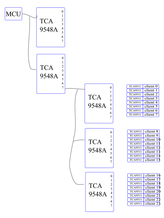
The first two TCA9548A is from the evaluation board, I want to use one of the I2C channel and further fan out to 24 slots. For each slot, I want to use one or more SI18IS606 to convert the I2C to SPI and also an EEPROM.

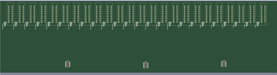
the board size will be ~300x100mm

Is such approach feasible?

Do I need TCA9511 before TCA9548A? If the 3 TCA9548A is about 100mm each?

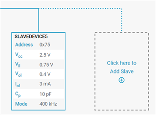
How to estimate the capacitance here?

  • This can be possible.

    All enabled bus segment are connected together, so their pull-up resistors act in parallel. All devices must have enough drive strength for that (i.e., the total current should be less than 3 mA).

    Traces have roughly 1…3 pF/inch. (If the capacitance makes the rising edges too slow, you can reduce the speed.)

  • Thank you for the reply, I got more follow up questions here: 

    Does the TCA9511 reset the IOL limitation for each segment?

    If the bus is 3.3V, and I add a TCA9511 before the three TCA9548A to isolate the IOL requirement from the previous stage, Does the following statement true?

    1: if only one segment enable is allowed at a time, the pull-up resistor for the TCA9511 and the TCA9548 can be as low as 2*1.1K ohm.

    2: If all the segments enables are allowed together, the pull-up resistor for the TCA9511 should be greater than 24*1.1K, say > 27K ohm?

    3: what is the limitation for using high pull-up resistor, e.g just use 100K ohm everywhere? My understanding is that reduce the RC constant of the trace, and effectively reduce the bus speed. Then how to calculate the speed limitation?

    4: For each client, because that is behind a TCA9511 buffer, so the IOL 3mA can be calculated independently, is this correct?

    Thanks

  • And I was expecting the TI I2C designer tool can help me simulate some of these bus buffer, mux, but I could not add these chips on the cloud evaluation version. Am I missing something or that is not in the scope of the I2C designer tool?

  • 0. You need 3 mA to get 400 kHz on a 400 pF bus. On a smaller bus, you do not need as much current.

    1. All resistors that are parallel must have total value of at least 1.1 kΩ. Two TCA9548As in series create three bus segments, all of which should have resistors, so you should have 2× 3× 3.3 kΩ (or larger).

    2. Yes.

    3. Yes, the pull-up resistors and the capacitances on your board form a low-pass filter. When your resistors are too large, the rising edges are slower; to ensure that they eventually reach VCCx, you might need to reduce the speed.

    4. Yes, the TCA9511A is a buffer and isolates the segments from each other.

  • Hi Gang,

    Your desired design of cascading two TCA9548A switches in to three TCA9548A switches is possible. As Clemens was stating, all devices on the bus need enough drive strength to pull the bus to an output LOW state (respecting total current should be <3mA per I2C standards). 

    1pF-3pF / inch in PCB design is a good estimation to follow when designing.

    Does the TCA9511 reset the IOL limitation for each segment?

    TCA9511 is a hot swappable I2C buffer that effectively re-drives the I2C bus, therefore "resetting" the IOL limitation for each segment and also separating bus capacitance between the IN/OUT sides of the device. 

    1: if only one segment enable is allowed at a time, the pull-up resistor for the TCA9511 and the TCA9548 can be as low as 2*1.1K ohm.

    You can have 1.1kohm total on input side of buffer, and 1.1kohm total on output side of buffer. But you must keep in mind that every branch on the output side of the buffer may appear in parallel with any active downstream channels activated. TCA9548 is a passive device, so 1.1kohm on the input side, and 1.1kohm on the output side of the switch will have an effective pull-up resistance of about 1.1kohm || 1.1kohm = 550 ohm, which is too strong of a pull-up resistance. 

    2: If all the segments enables are allowed together, the pull-up resistor for the TCA9511 should be greater than 24*1.1K, say > 27K ohm?

    I believe you would change this to 25 * 1.1kohm to include pull-up on the MCU side. So pull-up resistor on each channel > 27.5 kohm.

    3: what is the limitation for using high pull-up resistor, e.g just use 100K ohm everywhere? My understanding is that reduce the RC constant of the trace, and effectively reduce the bus speed. Then how to calculate the speed limitation?

    Clemens answered this question well. 

    4: For each client, because that is behind a TCA9511 buffer, so the IOL 3mA can be calculated independently, is this correct?

    This is correct.

    And I was expecting the TI I2C designer tool can help me simulate some of these bus buffer, mux, but I could not add these chips on the cloud evaluation version. Am I missing something or that is not in the scope of the I2C designer tool?

    When using the I2C designer in the cloud, look for the "Click here to Add Slave" box to add another device from which you can select other TI devices. 

    Regards,

    Tyler