This thread has been locked.

If you have a related question, please click the "Ask a related question" button in the top right corner. The newly created question will be automatically linked to this question.

TIOL1115EVM: Fault while connecting the TIOL1115EVM to STM32 Microcontroller

Part Number: TIOL1115EVM
Other Parts Discussed in Thread: TIOL1115, TIOL1113

Hello,

The pins on the TIOL1115EVM are connected to the STM32 Microcontroller as following:

Enable pin as output pin with internal pull down resistor

Wake pin, and Nfault  as input pin with Interrupt on falling edge with internal pull up resistor

TX to TX , RX to RX and GND from TIOL to GND on STM32 nucleo board.

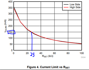
The Jumper for Enable (JMP 5) is enabled by connecting it to VCC In/Out and the Jumper for ILM_ADJ (JMP 1) is connected to 25K resistor.

There are 3 cases that might be helpful for diagnosis of the problem i am facing:

1. When i connect the MCU pins to TIOL1115EVM as described above and power the MCU the Nfault led lightsup indicating a fault without the master and the +24V connected to TIOL, but it immedtiately goes away when the two grounds are separated.

2. when i first power on the TIOL1115EVM through the master without the MCU being connected, it still indicates the fault and Nfault drops from 5V to 2.5V when the IOLink master tries to communicate and sends the wakeup pulse, although the wakeup pulse is recognised by TIOL it immediately triggers the Nfault pin led and the wake pin led on.

3.  When i connect the Master and the respective pins on the MCU and power on the device and MCU, the wake up is recognised as it lits up, but the Nfault also light up immediately and voltage is 0V indicating a error. 

What can be the reason for that, i have +24V stable Voltage so under voltage does not seems to be the reason , over temperature also does not seems to be the reason because it is in a ventilated open space and 

I am unsure where to measure for the over current condition?

The RX line also always just transmits a +5V constant signal after the wakeup is recognised by TIOL1115EVM.

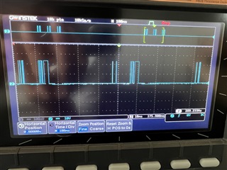
Above is the scope when CQ and L- is monitored without connected to the device.

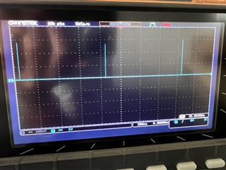
Above: Scope when monitored between CQ and L- when connected to TIOL1115EVM only (no Microcontroller) and wake led lit.

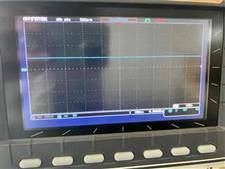
Above: RX and L- when monitored with CQ line connected to TIOL1115EVM and Wake Led lit (low level).

  • Hello Chirag,

    The first thing to do is to remove the jumper from the EN pin on JMP5 if the MCU is connected to the EVM.  This jumper is only needed if the EVM is used by itself where the jumper is needed to tie the EN pin High or Low.  But when the MCU and jumper are both connected to the EN pin, the MCU will not be able to control the voltage on the EN pin.  Because the jumper is connected to the VCC_IN pin, the TIOL1115 driver will always be enabled and prevent reception of data from the Master.

    The over current fault is a condition of the current flowing into or out of the CQ pin exceeding the current limit that is set with the resistor on the ILIM_ADJ pin.  With a jumper on the JMP1 header between the ILIM_ADJ pin and 25k will set the CQ current limit to approximately 150mA.

    The scope plot of CQ and L- when connectd to TIOL1115EVM only (no Microcontroller) and wake led lit shows the device is likely experiencing a current fault detection and is trying to auto recover by periodically enabling the CQ driver and checking the current. 

    Can you verify the load on the CQ pin is correct and will not try to consume more than 150mA?

    Can you try to not connect the CQ pin to the EVM and just connect L+ and L- to see if the over current condition fault is removed?  Basically, can you simply power the EVM with 24V and see if you can manually control the CQ output from the TX and EN pin jumpers and also see the RX signal changing state as well? 

    If that works, then the CQ pin to the EVM and see if it creates the fault.  If so, then debug the reason there is so much current flowing through the CQ pin to the Master.

    Also, you can just try to connect the MCU board to the EVM without the CQ signal present to see if it can control the CQ and RX voltage levels through the TX and EN pins.  Just remember to remove the EN and TX jumpers. I would recommend always keeping the ILIM_ADJ pin set to either the 25k or the potentiometer to avoid the current fault and auto recovery circuit from becoming disabled.

    Is the MCU board operating at 5V, or is it 5V tolerant?  The TIOL1115 device that comes with the EVM is the 5V version of the transceiver.  If your MCU board requires a 3.3V transceiver, then the TIOL1115 would need to be replaced with the TIOL1113 device.

    I would also verify the GND and L- is common or the same for all boards in the system.  It is possible for there to be different or floating grounds in multi-board setups particularly when one or more boards are powered from a non-grounded or isolated supply or USB cable.  Different grounds can create current flow between the boards and lead to fault conditions.  Since I don't know your setup, you should verify the GNDs are the same throughout the system

    Regards,

    Jonathan