This thread has been locked.

If you have a related question, please click the "Ask a related question" button in the top right corner. The newly created question will be automatically linked to this question.

TUSB213: DC Boost accuracy issue

Part Number: TUSB213

Hi expert,

My customer is using TUSB213 in their project. Could you please help check the voltage accuracy of DC boost? Because customer want to use this spec to calculate the max voltage of USB and want to know the max divation value of it. But I don't find the spec in datasheet. Many thanks!
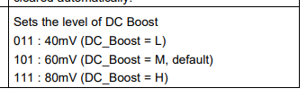
BR,
Jiaqi

  • Hi Jiaqi,

    Unfortunately, we do not spec deviation for DC Boost output levels in the datasheets, however, we do have HSpice models which have more information regarding the DC Boost levels. If your customer has an NDA with TI, if you can send me their NDA ID, I can get that sent to you.

    Thanks,

    Ryan

  • We obtained the goods from the agent - Arrow. May I ask if we can provide Arrow's NDA ID is ok?

  • Hello,

    If possible, it would be preferable to receive the NDA ID TI shares with the customer using the device.

    Thanks,

    Ryan

  • Dear Ryan:

          We finished the NDA just now,the NDA ID is "ICMNDADMA_9390"。Can you help to confirm the accuracy of the DC boost of TUSB213?Thank you very much!

  • Hello,

    Ok, will do, thank you for the help. If you don't mind me asking, what is the name of the customer that is using this data?

    Thanks,

    Ryan

  • Dear Ryan:

           Thanks for you reply!

           Our company is Tricheer,and our customer is Denso Ten.

           Thanks a lot!

  • Hello,

    Ok, got it! I sent you a friend request on E2E to send them to you, but in the meantime, I have sent them to Jiaqi over E2E PMs if you want to reach out and receive the files from them.

    Please let me know if you have any other questions!

    Thanks,

    Ryan

  • Dear Ryan:

        Thank you for sending the simulation file data!
        Since we are unable to view this simulation data, we would appreciate it if you could help us take a look. Can you see the accuracy of DC-BOOST?
        Additionally, I would like to confirm with you: What is the DC impedance (DCR) of the redriver when it operates in USB high-speed mode? For example: 0.2 Ω ± 0.05 Ω. Could you please help confirm.

        Thank you!

  • Hello,

    I will send a picture to your local FAE, I believe it should still be Jiaqi Wang. This information is NDA to TI, so please refrain from posting it on public forums.

    Can you see the accuracy of DC-BOOST?

    For accuracy, we do not spec for any variation for DC Boost, only the typical value of the boost, I.E 40mV, 60mV, and 80mV.

    What is the DC impedance (DCR) of the redriver when it operates in USB high-speed mode? For example: 0.2 Ω ± 0.05 Ω. Could you please help confirm.

    Additionally, we do not spec the DC Impedance of our redrivers while in high-speed mode.

    Please let me know if there is any other information you need.

    Thanks,

    Ryan

  • Thank you very much for your reply!
    Yes, our local FAE is still Mr. Wang Jiaqi.
      Because we need to theoretically calculate the amplitude of the USB signal after passing through the redriver, which still does not trigger the disconnect mechanism on the host side, we need you to provide the accuracy of the DC BOOST and the DCR value and accuracy of the redriver during operation.
      I'm sorry to have raised so many questions for you that are not included in the specifications. I think currently, all we need to know is the accuracy of DC BOOST and the value and accuracy of DCR to complete the theoretical calculation work. However, we also encountered a problem in production, which is how to effectively test the redriver on the production line. Because the production line cannot use an oscilloscope for eye chart testing, we have been thinking for a long time but have not found a reasonable and feasible detection plan. If you have any good suggestions, we hope you can give us your advice!
      There's nothing else left, thank you very much!

    大山

  • Dear Ryan:

          We have not received the data from Wang Jiaqi, maybe you have not sent the screenshot to Wang Jiaqi. Because I have to report the progress of the problem to the customer tomorrow, please be sure to reply today, thank you!

  • Hello,

    Understood, and no worries about the questions! I sent you a PM over e2e with some more information regarding DC Boost, hopefully that gives clarification for DC Boost levels and information we have for them. Also, please keep in mind that this information is NDA to TI, so please only share with others who have NDA with TI.

    For DCR, 3Ohms can be defined as typical for through-put impedance, but otherwise, we have not tested internally to monitor these values, so I cannot verify what variance there is if any in the trace.

    For detection plan, while we do not have any ways to test the redriver electrically without an oscilloscope, you may be able to try functional tests instead, I.E Plugging in a flash drive and reading and write to it with files of various sizes, either generated using a read/write tool or files you already have, to see whether the redriver is able to ensure functionality regardless of file size or transfer time. As such I would recommend looking at functional testing if possible, especially ones similar to your use case. Those may be able to help you.

    Please let me know if you have any other questions!

    Thanks,

    Ryan

  • Dear Ryan:

         Thanks for your support!

        Regarding the detection of the Redriver function, we have seen the following description in the specification book:

    PIN definition

        We would like to ask if it is possible to use the level state of this pin to detect whether the Redriver IC is working properly?
        Alternatively, can we add an indicator LED outside PIN8 (VREG)? If VREG has an output, it indicates that the redriver IC is working properly. This solution needs to confirm the output capability of VREG and whether it can support the operation of external LEDs without affecting the normal operation of the chip.
        I hope to receive more confirmation information from you.

        Thank you very much!

  • Dear Ryan:

        Thank you for your reply!
        The DCR you mentioned is about 3 Ω. May I ask if this is the working DCR or the non working DCR? We tested that the DCR of the redriver is approximately 3 Ω when it is not working. We cannot test the DCR during work. So please help confirm again.
        In addition, when the DC BOOST of the redriver is set to 40mV, we compared the signal amplitude of the DP/DM when the redriver is in operation and not in operation, and the difference is about 25mV. So I would like to ask if it is possible to detect whether the Redriver is working properly through this difference in DC level?

        Thanks a lot!

  • Hello,

      We would like to ask if it is possible to use the level state of this pin to detect whether the Redriver IC is working properly?

    Yes, we actually do encourage using this pin as a sort of debug indicator. When this pin is high, that means the device detects a high-speed signal, and is actively boosting the signal coming through it.

        Alternatively, can we add an indicator LED outside PIN8 (VREG)? If VREG has an output, it indicates that the redriver IC is working properly. This solution needs to confirm the output capability of VREG and whether it can support the operation of external LEDs without affecting the normal operation of the chip.

    If you wanted to, yes, you could use an LED with the VREG pin, as it outputs 1.8V when operating in high speed, please ensure there is a .1uF capacitor connecting it to ground.

        The DCR you mentioned is about 3 Ω. May I ask if this is the working DCR or the non working DCR? We tested that the DCR of the redriver is approximately 3 Ω when it is not working. We cannot test the DCR during work. So please help confirm again.

    Sorry, I should have been a bit clearer in my previous response. TI has not tested for DCR in the DP/DM lanes of the device, so I am unable to say whether this DCR is for unpowered as well as powered or not. Additionally, we have no information for DCR values.

    In addition, when the DC BOOST of the redriver is set to 40mV, we compared the signal amplitude of the DP/DM when the redriver is in operation and not in operation, and the difference is about 25mV. So I would like to ask if it is possible to detect whether the Redriver is working properly through this difference in DC level?

    Yes, if there is a difference in signal amplitude while comparing with the device is on or off, then you could consider that one way to determine if the redriver is active or not.

  • Dear Ryan:

         Thanks for your reply!

         Sorry to bother you again! Because you did not reply to me, will the driving ability of VREG be affected after adding LED detection, and will it affect the normal operation of the driver? Please confirm again.

         Thank you very much!

  • Hello,

    Sorry to bother you again! Because you did not reply to me, will the driving ability of VREG be affected after adding LED detection, and will it affect the normal operation of the driver? Please confirm again.

    Ah, I see, sorry about that, I misinterpreted what you were asking for. Additionally, I do have some more information for this pin.

    I would recommend NOT connecting an LED to this pin, as VREG is a regulator pin used for filtering, so anything which could draw a high current or muddy the pins signal may cause issues. As such, I would recommend leaving then pin as recommended by our typical application.

    Please let me know if you have any other questions!

    Thanks,

    Ryan