This thread has been locked.

If you have a related question, please click the "Ask a related question" button in the top right corner. The newly created question will be automatically linked to this question.

PCA9306: Slave interface signal quality issue

Part Number: PCA9306

Hi

When my customer tested the topology of BMC (Master)-PCA9306-slaves.

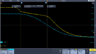
They found that there was an obvious groove on the falling edge of SDA in the read direction sent by different slaves measured at PCA9306, with the following two phenomena,

As shown in Figure 1 (1.157V~1.216V), Figure 2 (0.485V~0.549V).

Testing the read signal on the BMC side did not find this problem; please help confirm whether this problem is risky?

  • Hi Matt,

    This event is what our team likes to call "passFET hangtime". Its not an official term, but it is the phrase we use for this type of behavior. I am actually in the process of writing an application note to describe this effect in more detail. I am also using the PCA9306 for my testing, and am able to replicate similar scope shots to that of the customer. 

    This is a result of an imbalance of charge built up on parasitic bus capacitance separating the two sides SDA1 & SCL1 and SDA2 & SCL2. When one side drives low, it begins to drain the charge of side 1's parasitic bus capacitance to GND. While draining off the charge, this lowers the side 1 voltage turning on the internal passFET connecting side 1 to side 2 because the Vgs becomes > Vth of the internal FET. Vgate = VREF1 + VTH where Vth = ~0.6V. Once the internal passFET turns on completely, it connects side 2's parasitic bus capacitance therefore, it must drain the charge from an additional capacitive load from side 2. Here are some of the scope captures taken in lab. 

    The length of the hangtime is dependent on supply pull-up voltage of each side, parasitic bus cap, and the strength of the open-drain driver. You can see that the yellow signal effectively "hangs" for a period of time before it is allowed to transition to a VOL state. This effect only occurs in the nano second range, even in my "worst case" scenario in the second scope, the bus hangs for roughly ~111ns. In I2C, this would not interfere with the data. 

    For the customer scope capture provided, it looks like the time scale shows the event occurring for 302.135us - 302.130us = ~5ns. Since this occurs in such little time compared to the overall speed of I2C 100kHz/400kHz/1MHz, I would not suspect this occurrence to be any issue. In the second scope capture it looks like the customer is experiencing a little non-monotonicity in their system possibly from longer cable/trace lengths / excess wiring. 

    Regards,

    Tyler

    The difference in my scopes from showing a continuous step vs. a dual step like the customer is seeing is probably a difference in sampling and scope performance, as well as a difference in inductive loading between my system and the customer system.