Hello Expert,
We are considering to use this part at multiple connection.
However, we are not sure whether to place this part on both sides or one side.
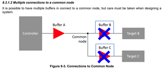
Is it possible like below?
If not, could you please give me a guide?

Best Regards,
Michael
This thread has been locked.
If you have a related question, please click the "Ask a related question" button in the top right corner. The newly created question will be automatically linked to this question.
Hello Expert,
We are considering to use this part at multiple connection.
However, we are not sure whether to place this part on both sides or one side.
Is it possible like below?
If not, could you please give me a guide?

Best Regards,
Michael
Hi Clemens,
We don't need hot swap function.
Also there is no issue because we don't use this part now.
Should I only use one between master and slave? Or, I wonder if I should use one each for master and slave.
Best Regards,
Michael
I²C buffers split a large bus into several smaller segments. This is typically used when the total capacitance would come near the I²C specification's limit off 400 pF. (A rough estimate is 1 pF per cm plus 10 pF per device.)
Hi Michael,
I am still trying to understand the reason for using this device. Do you have a block diagram you could share with us?
TCA4307 is a hot-swap capable buffer with stuck bus recovery. As Clemens stated, buffers help to separate the total capacitance in an I2C bus into multiple segments. If the system designer has a heavily loaded I2C bus from the connection of too many target devices + long PCB traces + large input cap, etc. then a buffer is suitable to keep underneath the 400pF parasitic bus cap limit put on by the I2C standard.
The TCA4307 is capable of driving two I2C segments of 400pF, making up for a total of 800pF of parasitic capacitance effectively doubling the capacity of your I2C bus.
Please let me know if this makes sense, and if you have any more questions, feel free to reply back to the thread.
Regards,
Tyler