Hi Ti engineer,
Our company encountered the following problems when using sn65dphy440ss verification:
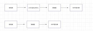
1, signal source-turn-board -MIPI display screen, the picture is normal;
2, add a turnboard with sn65dphy440ss chip,MIPI display, the picture is abnormal.
May I ask why the signal is abnormal after using the sn65dphy440ss chip? Are there any configuration errors? Attachment is the connection flow chart, sn65dphy440ss specification, sn65dphy440ss rotating board schematic.
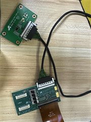
Attachment: The sn65dphy440ss sn65dphy440ss sn65dphy440ss chip transfer board and transfer board are four-layer boards, and the impedance is controlled at 100Ω
sn65dphy440ss.pdf
 fs-5020-d-phy-zjb-v1-20231124.pdf

