This thread has been locked.

If you have a related question, please click the "Ask a related question" button in the top right corner. The newly created question will be automatically linked to this question.

SN75LVPE5412: schematic check

Part Number: SN75LVPE5412
Other Parts Discussed in Thread: SN75LVPE5421

Hi

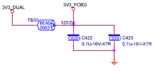
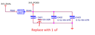
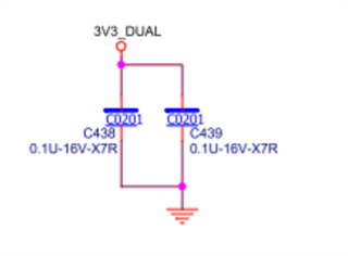
Could you help check the SN75LVPE5412 schematic and any need to adjust 

Also, I would like to ask about the SN75LVPE5412 and SN75LVPE5421. Are there any cable length requirements for these two on TX or RX? 

SCHEMATIC PCIEX16 GEN5 S.pdf

  • Hi Gareth,

    Here are my comments:

    • I am not familiar with the notation of this schematic software, does an "@" sign before the component value mean "don't include"?
    • I see that the RSVD1/2 pins are connected to ground through 0.1 uF capacitors. The guidance in the current revision of the datasheet says they should be grounded through traces or 0 Ohm resistors.
    • It looks like the devices are configured in Pin Mode with an EQ setting of Index 5 and a Flat/DC Gain of 0 dB, confirm that these are the intended settings
    • On the individual device power supplies I currently see two 0.1 uF capacitors and one 10 uF capacitor
      • The datasheet recommends one 1 uF capacitor per device instead of one 10 uF capacitor per device
      • The 10 uF capacitor can be shared between the four devices

    Best,

    Evan Su

  • Hi Evan

    1. Yes, the "@" symbol indicates that this component should not be populated.
    2. The circuit has been updated to 0 ohms to GND.
    3. As information about the length of the current circuit is not yet available, please configure it based on these default values for now.
    4. The remaining 0.1uF has been modified.

    The modified circuit is attached. Please assist in reviewing for any other issues. Thank you!

    SN75LP.pdf

  • Hi Gareth,

    Thanks for the update. I see the RSVD pins have been modified, however I think the customer was confused about my decoupling capacitor suggestion:

    It looks like they just removed the 10 uF capacitors from the device 3V3_PCIEx power buses, while my suggestion was to replace them with 1 uF:

    One 10 uF capacitor can be placed on the shared power bus here:

    Best,

    Evan Su