This thread has been locked.

If you have a related question, please click the "Ask a related question" button in the top right corner. The newly created question will be automatically linked to this question.

TUSB321AI: USB C - Not detecting polarity - DIR signal CC1/CC2

Part Number: TUSB321AI
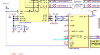
Other Parts Discussed in Thread: TUSB321

Hi,

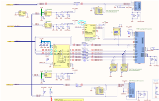
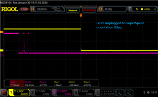
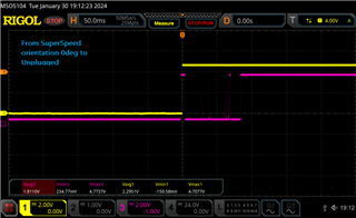
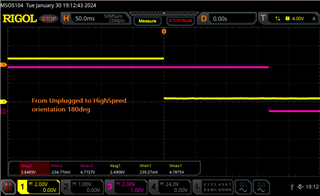
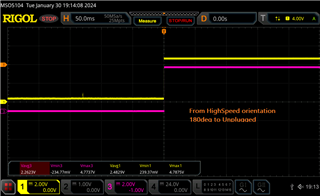
We are debugging the USB C connector. We are able to run on SuperSpeed (3.X) for one orientation; but for the other orientation it only gets HighSpeed (2.0)

I have been following the discussions here on E2E, but so far I can't find what can be the issue.

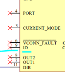
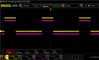
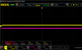
What I have seen so far, is that the DIR signal always have the same value no matter the way I plug something on the USB connector. CC1/CC2 pins do change value.

I found some errors on our design compared to the guidelines. But even patching it doesn't seem to solve it.

Any idea what could be the issue? Thanks a lot.

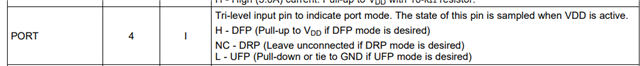
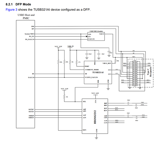
The intended mode is DFP. 

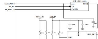
Also tried with VBUS_DET floating as in datasheet suggests for this mode, but not an improvement either.

When I patched the VDD to +5V_SW, now it doesn't detect at all one of the orientations. What can it be?

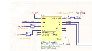
If I pull down the SEL pin on U16, then the polarity of the connector is reversed. 

Thank you for your insights! 

Best,

Cora

  • Hi Cora,

    I see the ID pin is left NC in your schematic. This pin is typically used to control the Type-C VBUS switch.

    How do you control the Type-C VBUS?

    We've had cases where not controlling the VBUS leads to issues with detecting one orientation.

    Best,

    Shane

  • Hi Shane!

    I saw it! I took it from the reference design guidelines from Toradex. (Here is the link to the documentation:

    https://docs.toradex.com/101123-apalis-arm-carrier-board-design-guide.pdf  - go to Figure 36 / page 40 )

    There they have ID pin floating, and the VBUS switch is controlled by im8x pin

    I will patch it and try it, although now that ID pin is floating, when measuring with the oscilloscope I can't see any change of voltage there going on. But will try! 

    Thank you!

    Best,

    Cora

  • Hi Shane, I would like to ask to; is it needed then for sure the VBUS_DET connected even for DFP mode?

    On the datasheet, section 7.3.3 VBUS Detection, it is suggested that VBUS_DET pin can be left unconnected. 

    https://www.ti.com/lit/ds/symlink/tusb321.pdf?ts=1705996886206&ref_url=https%253A%252F%252Fwww.ti.com%252Fproduct%252FTUSB321 

    Thanks!

    Cora

  • Hi Cora,

    is it needed then for sure the VBUS_DET connected even for DFP mode?

    It is ok to leave VBUS_DET unconnected in a DFP only application. It is also ok to leave it connected to the VBUS as you have done.

    I took a look at that reference schematic and see the PORT pin is left NC, which would be Dual role port (DRP) mode on the 321.

    If you want DFP only mode, pull this pin up to VDD.

    when measuring with the oscilloscope I can't see any change of voltage there going on.

    The ID pin is an open drain output. You would need to pull it up to 3.3V or no voltage will appear on the line. Here is the typical application schematic in the 321 datasheet to demonstrate how ID is implemented.

    If your VBUS switch has a low-enable pin, you can route ID directly to the enable pin on the switch. ID will go low when the 321 expects to provide power on VBUS.

    Let me know if you have any questions.

    Best,

    Shane

  • Hi! 

    I have updated the patches as suggested:

    PORT pin to 5V with 4.7k

    ID pin to 3.3V with 200k 

    VBUS_DET pin left floating

    I still get the same results: In one orientation of the flash memory USBC I get SuperSpeed, in the other orientation I get HighSpeed only

    I can't see the ID pin go low when plugging in a flash memory in either both positions.

    DIR pin stays always the same value in either both positions.

    What else could it be? Where could I measure? 

    Thank you! 

  • HI! 

    In addition to my previous comment. I can see CC1/CC2 voltages to be 440mV and 400mV (switching between this two values depending the orientation of the flash memory), but DIR voltage is always 300mV 

    Which makes when it goes to SuperSpeed mode, I get signal on the Channel C;

    but when changing polarity of the flash memory, there is signal in both Channel C and Channel B (peaks to -40mV), and also signal on the HighSpeed lane (D+/D- 2.0 signals) 

    Something seems off in the DIR/SEL pins 

  • Hi Cora,

    I agree that something seems off with the DIR pin. I want to be sure the CC negotiation is happening correctly.

    1. Can you verify the following on the CC1 and CC2 lines? Seeing a scope picture would be helpful to debug.

    • Are the CC1 and CC2 pins at 5V when nothing is plugged in to the type-C receptacle?
    • The CC1/2 lines on the DFP should both be 5V, then one will drop to a lower voltage after device attachment.
    I can see CC1/CC2 voltages to be 440mV and 400mV

     Here is a good resource that explains the CC orientation detection. Are you seeing one, or both CC pins drop in voltage after attachment?

    2. Is the VBUS being enabled before the device attachment? VBUS should not be enabled until after the CC pins negotiate attachment. See this E2E post for a past case on the same problem. (Their issue ended up being that the chip was rotated 90 degrees incorrectly!)

    3. Have you tried using a different flash memory/UFP device? I want to be sure the UFP is not the issue.

    Best,

    Shane

  • Hi!

    I have been trying some stuff.

    1. Replaced 321 for a new one (to make sure it is a healthy IC, and checked the orientation)

    2. Left this set up:

    With this set up, I can see on CC1/CC2 voltages (CC1 - yellow // CC2 - purple):

    •  2A. When unplugged flash memory: (Is the oscillation normal?)

    • 2B. SuperSpeed detected (orientation 0deg):

    • 2C. High Speed detected (goes through 2.0 lines) (orientation 180deg):

    For all cases, SEL / DIR pin is 0V - no change. 

    ------------------------------------------------------------------------

    Also, I have another board where I patched those pins and swapped them. And there, the behavior is the same, but the orientation of the flash memories give me the SuperSpeed and Highspeed the opposite as in the non-swapped board. 

    (Saying this to confirm that the lines are good routed and functioning) 


    ----------------------------------------------------------------------

    For your questions: 

    1. Now I can see the voltages on CC1/CC2 changing (As the images)

    2. VBUS_DET is left floating. VBUS is connected to 5V VDD. Shouldn't it?

    3.Yes; I have tried different USB C flash memories, same result. 

    Thanks a lot! 

    Best,

    Cora

  • Hi Cora,

    VBUS is connected to 5V VDD. Shouldn't it?

    VDD and VBUS should not be connected together for a DFP. You want VDD to first power the TUSB321, then the 321 should control when VBUS is applied. You can see how this is would look from the typical application in the datasheet:

    Now I can see the voltages on CC1/CC2 changing (As the images)

    That oscillating makes sense for a DRP, however if you are in DFP mode CC1 and CC2 should be held at 5V constantly. Do you see this behavior on the 321 after pulling PORT high or is PORT still NC?

    Could you show the CC lines at the point when the device is attached? (The transition from unattached --> attached). It seems your pictures are after the device is already attached, when both CC lines are at low voltages.

    Best,

    Shane

  • Hi Shane!

    Thanks for pointing out the DRP mode and the PORT configuration Thumbsup

    The previous images where with PORT floating.

    Following images are with PORT pulled up. (no more oscillating)

    ID pin is also is pulled up.

    VBUS_DET is floating. 

    CC1/CC2 voltages (CC1 - yellow // CC2 - purple):

    SEL/DIR pin is always the same (no change when plugging in either orientation) 

    (I removed the ESD protection for measuring)

    Thanks a lot! 

    Best,

    Cora

  • Hi Cora,

    Are you able to share the schematic as it is now? I know there have been some changes since the original one you shared and want to be sure I have the right idea.

    Is the 3.3V_SW power rail that connects to DIR going high before the VDD pin on the 321?

    DIR can potentially back-drive the device if it goes high before the 321 is powered on. If back-driving occurs the 321 could have issues initializing.

    Best,

    Shane

  • Hi Shane,

    It works now, thanks for all the help!

    Apparently, the two boards I had, the 321 was damaged; once replaced for a new one, it worked as it should! (Voltages on CC1/CC2 where 5V when unplugged and went low when plugged flash memory)

    Also, on my design VDD (pin12) was connected to VCC_USBH4 (Connector) instead to the 5V_SW (System) <- This had a major impact, once patched on a new-healthy 321, it worked!

    This is my working set up now :) It detects SuperSpeed in both orientations/positions of the USBC flash memory.

    Thanks a lot! :D

    Best,

    Cora