This thread has been locked.

If you have a related question, please click the "Ask a related question" button in the top right corner. The newly created question will be automatically linked to this question.

PCA9546A: No Ack when sending the address (0x70) + Wr to chip.

Part Number: PCA9546A

Hi.

First, some background.

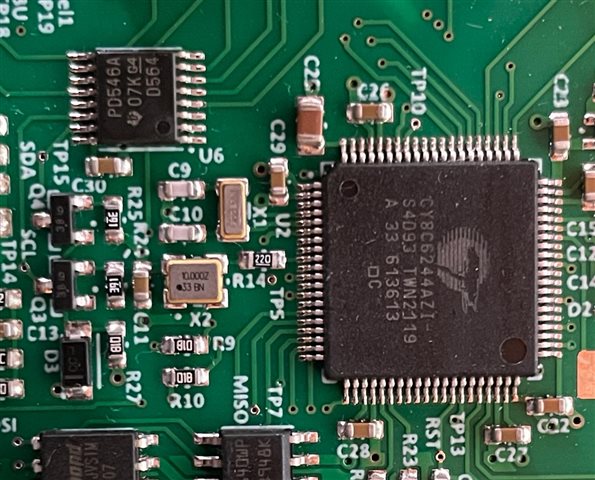
I am developing a unit with four identical slots for plug-in modules. These modules will be identical insofar as the I2C devices on them and therefore have the same addresses. To manage this, I added a PCA9546A chip to select the slot I want to communicate with. The slots are within an inch (25mm) from the PCA9546A which in turn is about the same distance from the MCU controlling it. I have two PNP transistors configured for constant current pull-ups on the lines and have also replaced it with 1k5 resistors to be check if that was an issue. I am running at 100kHz.

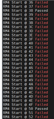
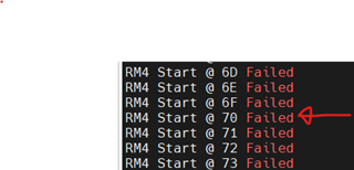
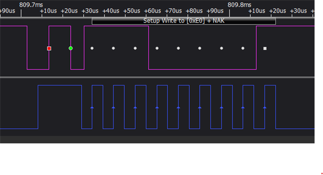
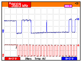
When addressing the PCA9546A to select a channel, the SDA and CLK lines output the correct signals ( as verified by oscilloscope, logic analyzer and Active-Pro debugger ), but there is no Ack from the PCA9546A. I changed the software to scan all I2C addresses from 0 to 0x7F to look for a device, but it is not found.

I then soldered pins onto the board and hooked up an external I2C device ( bus expander ) and the scan found the address at 0x27, I then bypassed the PCA9546A and essentially connected the MCU directly to one of the slots and plugged a module in and did the scan again which detected both the I2C devices on the module at addresses 0x38 and 0x50 where they belong..

I think I can safely say that the issue is not on my hardware/firmware other than the PCA9546A chip. I checked the board layout several times and all connections are ok. The 3 x address pins are grounded, the /Reset pin goes to the MCU and is driven correctly. The SDA and SCL lines are also correct, as verified by the other I2C devices. 

I had 5 x boards made for prototypes and tested all 5 with exactly the same results, so it should not be a single chip issue.

My question is, has anybody else had the same issue?

Best regards

Chris
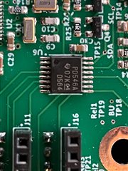
  • PS. I ordered 10 x PCA9546APWR chips from the TI store and will mount some on breakout boards and test them once they arrive.

  • Hey Chris,

    Thanks for reaching out here and providing all the details. A few things to note here:

    1. Can you provide the schematic/layout? Just to double check routing and connections such as SDA and SCL. We've seen before that these have been swapped on accident. 

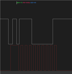
    2. I'm a bit confused by the waveform provided - this particular image doesn't represent a start condition (clock line needs to be high when SDA goes low). Maybe I'm mistaken by the intent of the scope shot. 

    3. Glad to see you already ordered some parts to mount to a breakout board. Ideally no issues with this, then we will be able to tell there's a difference between the PCB implementation and the breakout board. 

    Regards,

    Alex

  • Hi Alex.

    Thanks for the reply. Please provide me with your TI email address so I can send you the info you requested. I cannot post schematics on a public forum.

    I will look into the start condition, but thinking back, this was not a trace of the last runs, as I had to use my logic analyzer pins to bypass the PCA switch. I will rerun it as soon as I sort out more connections to the board.

  • Hi Alex

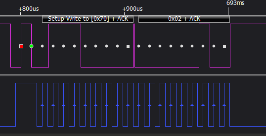
    The green dots on the screenshots indicate the start condition and the white square block indicates where the Ack should be.

    The first one is from one of the devices responding correctly ( Addr 0x38 ) with a second byte sent and the second (Addr 0x70) is from the PCA switch which does not respond with the Ack. To me this indicates that the SDA and SCK lines are ok, but I will doublecheck it again.

    Both are from the same scan of all addresses from 0 to 0x7F 

  • Hi Alex

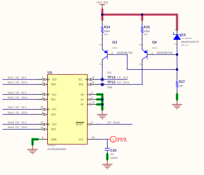
    To speed things up, I will provide you with the info you requested without divulging proprietary information. Please see the other info I also provided in the other replies.

    Processor connections:

    PCA9546A connections: I also replaced the transistor circuits with 1k5 pullup resistors just to test.

    Processor configuration:

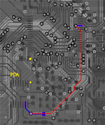
    PCB for SDA:

    PCA pin15 to MCU pin 35. Yellow dots are pin 1.

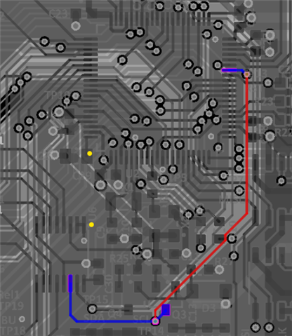
    PCB for SCK:

    PCA Pin14 to MCU pin 34

    To help to visualze the pcb, here is a picture. Rotate 90deg counterclockwise to align with above layouts

    Please let me know if there is anything else you need.

    Regards

    Chris

  • Hi Chris,

    Thanks a lot for all of the additional info. 

    How many channels are on at any given time? Just 1, or more?


    Is it also possible to look at the I2C signal from a scope perspective and not a digital analyzer? We can't see the RC or VOL values that are important to I2C analysis. Is it possible to probe the SDA/SCL bus to the switch?


    Any update on the samples that were ordered? I'm really curious to see if the device works when bypassed on the PCB via a breakout board.

    Apologies for all the questions here. This one is a bit trickier to get a solution to right away since there's so many parts involved. 

    Regards,

    Alex

  • Hi Alex

    I think you are missing the point. I cannot even get an Ack from the switch when sending its address, so no channels are on. The switch is also the only I2C device connected to the MCU. When I connect the MCU directly to one of the slots carrying an I2C device, I can communicate with the other I2C devices without any issues.

    I am uploading a video to show the port expander responding to the I2C commands after bypassing the switch. Also attached is a scope trace of a 2-byte transmission, scoped at the MCU I2C connection to the switch.

    I received a notice from TI that the parts have shipped, but there is no delivery date yet.

    Regards

    Chris

  • That scope trace shows a working access to address 0111000; please show an access to the PCA9546A. (But the waveforms look OK.)

    The signal voltage appears to be 4 V. Shouldn't it be 3.3 V?

    What is the voltage measured at the /RESET pin?

  • Hi Clemens

    I rewired my board to connect directly from the MCU to one of the slots on my board. The PCA9546A and the expander are now both connected to the MCU and as such the signals are the same as seen on the scope trace. I also changed the firmware to address the expander as I need to carry on with my development. Sending the switch address will not make any difference to the signals, just different bits as was shown on previous logic traces submitted.

    The rest pin is at logic high, but even if it was low, according to the documentation, it should only affect the four outgoing channels.

    The voltage is a bit problematic as the boards in the slots runs on 5V logic while my MCU is 3.3V. The switch is supposed to handle the logic level translation but since it is bypassed, it is not happening. Having said this, before connecting directly to the slot, the signals looked the same on the oscilloscope, the levels were just between ~0,2V to ~3,1V.

    My feeling is that I have a batch of faulty chips that was populated on my boards as all 5 does not work.

    Let me give more detail on the process I followed to get to this conclusion.

    I made the SDA and SCL lines floating on the MCU, with the pullups still connected. I then hooked an Arduino board (Teensy 4.0) up to my board and ran an I2C address scan program and it could not "find" the PCA9546A. I then hooked an I2C expander from a character LCD display interface up to my board and ran my I2C address scan program and it found the expander at 0x27. It was then when I bypassed the PCA9546A to Talk directly to my slot modules and everything works as demonstrated. 

    Once I received the IC's I ordered from TI, I will first put one on a breakout board and if it works, replace one on my PCB for testing.

    Best regards

    Chris

  • Hi Chris,

    Thanks for sharing all this additional info. I think we are at a point where we want to see the results of the breakout board and PCB device replacement before further investigation. Please let us know once this has been completed!

    Regards,

    Alex

  • Hi Alex

    According to DHL, the parts will be delivered on Monday and I will do the necessary once I have it.

    Regards

    Chris

  • To all.

    It is time for me to eat a load of humble pie.Flushed

    All connections on the PCB to the PCA9546A are 100%, except there is no power on the Vcc pin.

    I received the parts I ordered and put one on a breakout board and it is seen when I do an address scan. With power on the Vcc pin, it also works on my PCB.

    I have given the company that do our PCB layout the info and they will correct it.

    Thank you for all your inputs, it is greatly appreciated,

    Best regards and have a great day.

    Chris