Hello,
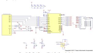
We want to use a TDP142 as redriver between a CPU DisplayPort output and a DisplayPort output connector.
We want to support the DP dual mode (DisplayPort/HDMI mode).
The TDP142 will be configured through I2C: pin 11/14 used to select I2C target address, pin 17 “F” or “1” to select I2C 1V8 or 3V3.
I2C general register 0x0A, bit5=0 (HPDIN is in default location)
For optimal power consumption:
Pin 23 (DPEN/HPDIN) will be connected to the HPD pin from DP connector (pin18)
Pin 24/25 (AUXp/AUXn) will be connected to AUX pin from DP connector (pin15/pin17)
In this mode we can read in datasheet that:
Pin 29 (SNOOPENZ/RSVD8) is reserved, but can we keep this pin floating?
Pin 32 (HPDIN/RSVD9) is reserved, but can we keep this pin floating?
For all the other reserved pins we have the remark (1) Leave unconnected on PCB, not this remark for pin 29 and 32, can you clarify?
Moreover, I do not understand why in I2C mode, the pin 29 has no more the SNOOP enable functionality.
With this SNOOP enable pin connected to the pin 13 from DP connector (HDMI/DP mode), the TDP142 has an easy way to know if we are in DP mode or in HDMI mode and automatically disable the snooping in case of HDMI.
Can you confirm that by analysis of the signal present on the AUX/DDC pins the TDP142 is able to detect that we are in HDMI mode (DDC data) or DP mode (AUX data) and take the right action concerning the power management?
Or does it mean that we will need to disable through the I2C the AUX snooping when we will be in HDMI mode?
If yes, this would therefore require intelligence in the code used to initialize the component through I2C and this code must know if we are in HDMI or DP mode!
Could you clarify?
Thank you


