This thread has been locked.

If you have a related question, please click the "Ask a related question" button in the top right corner. The newly created question will be automatically linked to this question.

TIOS101: Strange issue while test OCP function...

Part Number: TIOS101

Hi Team,

customer tested the OCP function with the below schematics and found the problem.

V+=24Vdc, Vcc=3.3V, output is PNP or NPN type loading.

The test result as below.

output type

OCP startup value

OCP recover vaule

Note

NPN

68mA

67mA

remove R17 

PNP

68mA

15mA

R17 is 100k

May I know what is the reason of the different values for NPN and PNP type loading?

Thanks.

  • Hi Peter,

    Can you please clarify a few things for me?

    What do you mean by "OCP function"?  Does OCP stand for something like Over Current Protection?

    Where is the current being measured? Can you indicate that in the circuit diagram?

    What is connected to the Output for both test conditions?  Is it ONLY the C7 capacitor?

    Can you explain the test steps being performed?  Specifically I'm not clear on what the difference between "OCP startup value" and "OCP recover value" is and what is being done between these two measurements. 

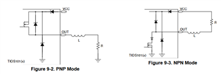
    Current flowing into or out of the OUT pin will be based on the external load.  In NPN mode, the device would sink current into the OUT pin from a load connected between the L+ and OUT pins as shown in the datasheet's figures in the Driving Inductive Loads section.  I don't see a current path in the schematic you provided that would provide the 68mA of current. 

    Likewise, for the PNP mode, the device would source current out of the OUT pin into a load connected between the OUT pin and L- (GND).  The schematic shows a 100nF capacitor as a load, and if this is the only load, it will eventually become charged and the current level will drop.  If the capacitor becomes charged during the startup phase of the test, then it may not draw the same level of current during the recovery phase of the test which would explain the reason for the lower current reading of 15mA.

    Regards,

    Jonathan