- Ask a related questionWhat is a related question?A related question is a question created from another question. When the related question is created, it will be automatically linked to the original question.
This thread has been locked.
If you have a related question, please click the "Ask a related question" button in the top right corner. The newly created question will be automatically linked to this question.
Tool/software:
Hi,
Q1. I believe that the variation in V_SENSE and V_SL ratio described in the Electrical Characteristics of the data sheet is temperature dependent, is this correct? Also, are there any other factors that cause variation?
Q2. If Q1 is temperature dependent, is it correct to assume that V_SENSE and V_SL ratio have a positive correlation with temperature?
Thanks,
Conor
Hi Conor,
Thanks for using the e2e forum.
Q1.) Yes, most variation comes over temperature, but other factors have a small effect as well, e.g. device variation from production or worst case input/output conditions.
For designing the schematic, we recommend using the min-/max values of the electrical characteristic for values like V_SENSE, as to provide some safety margins.
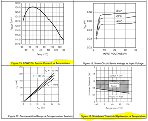
Q2.) The datasheet shows some graphs on parameters that are strongly dependent on temperature.
Please refer to these graphs regarding the temperature correlation.
Best regards,
Niklas
Hi Niklas,
Thank you for your detailed reply, I understand. I also have one additional question.
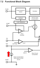
Regarding the direction of the current from the current source of the I_SENSE pin, is it correct to understand that it flows in the direction of the arrow in the diagram below?
Thanks,
Conor
Hi Conor,
Yes and no. Based on the block diagram, this current source source should be responsible for the external slope compensation to work, in case an additional slope compensation resistor is placed at the Isen pin. This is recommended for duty cycles above 50%, where subharmonic oscillation can occur.
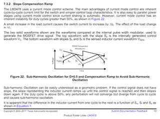
Chapter 7.3.2 goes into detail on how the slope compensation works.
There are two possibilities to adjust the point where Vsen and Vc collide with each other, either by steepen the Vsen upwards slope, or by steepen the Vc downwards slope.
I am not sure what implementation was chosen for the LM3478 device, but the effect on the regulation is essentially the same.
Best regards,
Niklas
Hi Niklas,
Thank you for your comment. My understanding is as follows.
To prevent subharmonics, Sn>Sf is required. Therefore, a ramp signal with a certain inclination is added to the on-state current slope to compensate for the larger slope at on-state.
There seem to be two methods of slope compensation.
A. A circuit method that adds a slope that makes the error amplifier output downward to the right.
B. A circuit method that adds a slope compensation current to the current sense output.
The effects of A and B are the same, but the latter is more common because it can be achieved simply by adding the sensed current, simplifying the circuit configuration. Looking at the circuit diagram, the arrow in the current source symbol makes it seem like A. I would appreciate it if you could comment, including whether my understanding is correct.
Thanks,
Conor
Hi Conor,
Yes, your understanding is correct.
I double checked with other controllers that have the same regulation as LM3478.
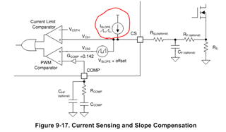
Here is the current sensing structure of LM5155:
Here the arrow is in the other direction, just as you initially pointed out.
I assume the arrow direction in the LM3478 does not indicate the actual current direction and is therefore misleading.
I will submit a datasheet fix for this.
Best regards,
Niklas