Tool/software:
Hi Team,
The customer will be using it in Basic mode.
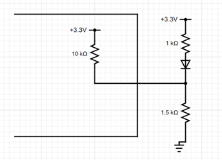
Could you provide a circuit diagram for strapping the LED pins?
I would like to know both for strapping to low and to high.
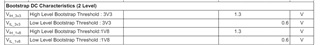
I have read the following text in the datasheet, but I would like more specific information.
"In BASIC mode, the LED polarity will always be active low. In the case that the LED pin must be strapped low, a 1 kΩ pull-up resistor in series with the LED should be used and a 5 kΩ pull-down resistor. This will result in the strap selecting 0. Please note that using higher resistance may decrease the brightness of the LED."
Best Regard,