A related question is a question created from another question. When the related question is created, it will be automatically linked to the original question.
If you have a related question, please click the "Ask a related question" button in the top right corner. The newly created question will be automatically linked to this question.
[FAQ] TUSB1142: How to properly connect the TUSB1142 FLIP pin to the TPS2583xA-Q1 CC controller
Part Number: TUSB1142 Other Parts Discussed in Thread: TPS25820,
Tool/software:
The TUSB1142 design uses the Flip signal from a TPS25820 to switch the SuperSpeed signals from a USB Type C connector. We are not able to get SuperSpeed to work at all.
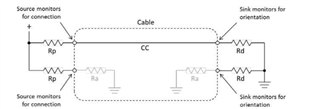
A USB Type-C uses the Configuration Channel (CC1 and CC2) to serve the following purposes:
Detect connection of the USB-C port
Resolve cable orientation and twist connections by configuring the establish DFP and UFP roles between two connected ports
Discover and configure power: USB-C current modes or USB Power Delivery
Discovery and configuration of optional Alternate and Accessory modes
The connect detection of the USB-C port occurs when one of the two CC lines pulls down. A Downstream Facing Port (DFP) or host will have both of its CC pins pull up with resistor Rp, and an Upstream Facing Port (UFP) or device will have both of its CC pins pull down with resistor Rd]. Once a DFP processor detects that one of its CC lines is pulled down, the DFP will know that a connection has been made.
Cable orientation is based on which CC line pulls down (if CC1 pulls down, the cable is not flipped; but if CC2 pulls down, the cable is flipped). For nonactive cables, the remaining CC line remains open; for active cables, the remaining CC line will pull down with Ra.
As a result, there are four potential data paths:
Straight unflipped: host TX1 and RX1 to device TX1 and RX1 with CC1 to CC1
Twisted unflipped: host TX1 and RX1 to device TX2 and RX2 with CC1 to CC2
Straight flipped: host TX2 and RX2 to device TX2 and RX2 with CC2 to CC2
Twisted flipped: host TX2 and RX2 to device TX1 and RX1 with CC2 to CC1
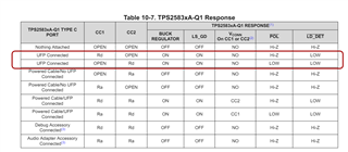
With the TPS2583xA-Q1 CC controller, its POL is an open-drain logic output. It signals which Type-C CC pin is connected to the cable CC line. This gives the information needed to mux the SuperSpeed lines. The POL is in a high-Z state when the CC1 pin is connected to the cable CC line. And when CC1 pin is connected, TX1/RX1 is the USB path. The POL pin is asserted (driving low) when the CC2 pin is connected to the cable CC line. And when CC2 pin is connected, TX2/RX2 is the USB path.
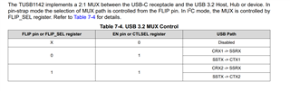
But for TUSB1142, when FLIP pin is driving low, TX1/RX1 is the USB path. When FLIP pin is driving high, TX2/RX2 is the USB path. So there is a polarity mismatch between the two devices.
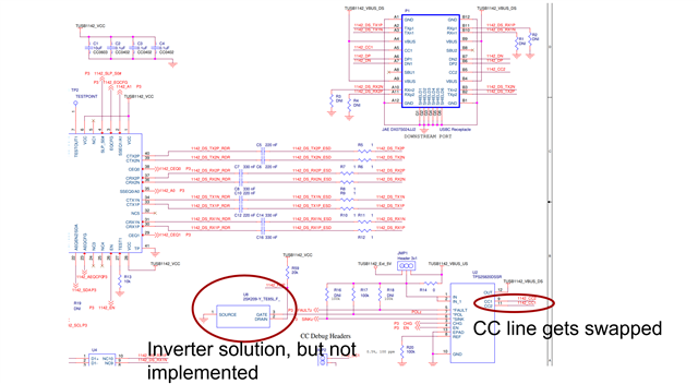
There are two solutions to solve the polarity mismatch:
1. You can swap the CC1 and CC2, connect CC1 from the Type-C connector to TPS2583xA-Q1 CC2, and connect CC2 from the Type-C connector to TPS2583xA-Q1 CC1 OR
2. Add an inverter on the TPS2583xA-Q1 POL pin
The TUSB1142 EVM implemented both options as shown below