


Tool/software:
What is Dual Mode
Dual mode or DP++ allows for a DP source to output a HDMI signal to a sink without using an active protocol converter. The DP source must be DP++ capable for dual mode operation. The key considerations when designing a dual-mode system is the AUX/ DDC bus connections on the source, and the main link connections for the DP signal.
Main Link Connections
The main links of the DP++ source will be mapped to the DP++ connector as follows.
|
DP Source Output Pins |
DisplayPort Receptacle Pins |
|
ML_Lane_0 (n) |
ML_Lane_0 (n) |
|
ML_Lane_0 (p) |
ML_Lane_0 (p) |
|
ML_Lane_1 (n) |
ML_Lane_1 (n) |
|
ML_Lane_1 (p) |
ML_Lane_1 (p) |
|
ML_Lane_2 (n) |
ML_Lane_2 (n) |
|
ML_Lane_2 (p) |
ML_Lane_2 (p) |
|
ML_Lane_3 (n) |
ML_Lane_3 (n) |
|
ML_Lane_3 (p) |
ML_Lane_3 (p) |
|
AUX_CH (p) |
AUX_CH (p) |
|
AUX_CH (n) |
AUX_CH (n) |
|
DP_PWR |
DP_PWR |
|
Hot Plug Detect |
Hot Plug Detect |
|
CONFIG 1 |
Cable Adaptor Detect |
|
CONFIG 2 |
HDMI CEC |
AUX/ DDC Connections
AUX and DDC are the video status and control busses for DisplayPort and HDMI respectively. The AUX interface is an AC coupled interface that communicated over 1Mbps Manchester encoded data. The DDC interface is a DC coupled interface that communicates via I2C, so pullups may be required.
As you may have noticed the DDC and AUX protocols are incompatible and must be gated so only one is active at a time. In the dual mode spec there is a cable adaptor detect (CAD) pin which can determine if a DP or HDMI sink is connected to the dual mode source. This CAD pin can be used as the control for the gating between the DDC and AUX bus.
An example implementation on DP++ AUX/ DDC can be seen below.
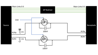
This implementation takes advantage of the switching properties of a MOSFET keeping the MOSFET open when CAD Is 0, and bypassing the capacitors when CAD is 1. This will allow for the AC coupled AUX signal to pass when a DP sink (CAD = 0) is connected to the system, and the DC coupled I2C signal to pass when a HDMI sink (CAD = 1) is connected. A key assumption in this implementation is that the required 3.3V pullups for I2C communication are placed on the HDMI sink DDC lines.