Tool/software:


Hello Eric,
As suggested by your team member, Ms Amy, this new thread is being opened for the CAN portion of the following post.
Please let us know if this is not the correct way to open a new thread.
Thank you,
Arun Patil
----------------------------------------------------------------------------------------------------
Arun Patil in reply to Eric Schott1
Hello Eric,
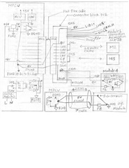
First of all, we thank your team for the prompt and precise reply. This system has multiple spurious/intermittent issues and changing LVDS topology to point-to-pont signaling with M-LVDS output levels at all 4 connectors would definitely address one major problem. We are in the process of building a prototype and shall keep you posted with testing results. We appreciate your inputs on CAN performance improvement and will have few units tested with the partial termination of 4.7k-ohms on all other four CAN nodes on modules. Please take a look at the attached diagram and note that the shield of cable is tied to 0V conductor (that is on FGND plane) on FFC1 (MPCU board side) and on the other end of the module side, it is also tied to 0V conductor through a FB. The 0V signal line and DGND of the module are on the same plane. The MPCU and all the modules are supplied with isolated power from a single DC to DC converter on the MPCU that gets its DC supply from a SMPS whose chassis is not grounded. Do you think the loop formed inside the cable by 0V conductor and the shield would be the cause for the spurious problem due to noise pick up? If so, would it be better to leave the shield open on the module end?
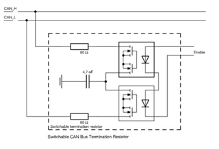
This system has the MCU with dual CAN controllers on the MPCU side but only one unit is used. The host (center) node is just 4 cm in stub lengths from the connector block (CN1, CN2, CN3, CN4). What if the MPCU is configured to use both CAN controllers, add another CAN transceiver (or use a dual XCVR) to make two host (center) nodes HN1 and HN2 on MPCU and each of them connected to a set of connectors (CN1-CN2 and CN3-CN4) midway between them so that the two modules connected to each host CAN node would appear as if they are end CAN nodes on a linear CAN network topology. In that case, all the end nodes (on modules) can have permanent termination of 120-ohms and both the host nodes can have switchable termination that can be turned on dynamically (processing module connection/identification signal) if only one module is connected to the host node. For instance, if three modules are connected to CN1, CN2 and CN3 connectors, the termination on the second host node HN2 will be switched on as the CN4 connector remains unplugged. Being a conventional linear CAN network topology, it will be a highly stable permanent long term solution to handle faster data traffic in future due to enhancement in the modules. We would appreciate your thoughts on pursuing this avenue.
Thank you,
Arun Patil
----------------------------------------------------------------------------------------------------
Eric Schott1 in reply to Amy
Hi Arun,
I was able to review the CAN portion of the block diagram you shared with Amy. I don't see any issues with the current layout and do not think there will be any concern with this topology assuming the data rate of the system is not very high.
The main concern with non-ideal bus topologies such as the star layout is the reflections of the signal interfering with the data during the sampling point of the bit. With lower data rates, the sample point is further into the bit so there is more time for the signal to settle before the bit state is sampled. For a harness with 2.5m long stubs, I don't expect this ringing to cause any issue with lower data rates such as 500kbps. However, there will likely be concerns with data integrity around 2Mbps or higher. If these faster data rates are needed, I would recommend the use of a CAN Signal Improvement Capable (SIC) transceiver such as the TCAN1462. CAN SIC transceivers are able to suppress the ringing in non-ideal CAN networks to allow for faster data rates on harnesses that are susceptible to ringing.
Apart from this, the rest of the design decisions look sound such as placing 60-ohms of termination all on the center node. My only small recommendation would be to include partial termination (~4.7k-ohms) on the stub nodes to help suppress ringing.
Let me know if you have any more questions.
Regards,
Eric Schott

