Other Parts Discussed in Thread: TCA6424
Tool/software:
The SLVUA59A board which I have been using has two slave i2C chips, the one that I am trying to communicate with is the TCA9539 with the address of 0x77.The other slave chip (TCA6424) on this board can have the address of 0x22 or 0x23 which I have no interest of using at a time. I grounded the pin 9 of the J1 in order to put this chip (TCA6424) in reset mode to eliminate any possibility of this chip interfering with the communication between the master and the slave(TCA9539) as I am trying to debug an issue with responses coming from the TCA9539.
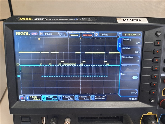
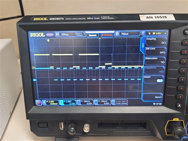
I supplied this board with +3.3v and connected the SDA &CLK lines coming out of the master (Micro Controller) to this slave chip (J8). The SDA & CLK lines, each have a 4.7K pull up resistors in their lines. When the software running in the master, receives any response from TCA9539, this chip does not push the data line all the way to zero level. The zero level by this chip in this board goes all the way to ~+600mv but not to zero. I have included below a screenshot captured by a scope as the master transmitted the address of 0x77 with the write command to the slave and then it received an ACK from the slave. Please take a look at the ACK received from the slave by the master. The ACK does not drop to zero level and my logic analyzer interrupt it as a NAK. Any response from slave including data read from registers which may contain ‘0’ in any of its bit pattern shows up above zero line (~+600mv) as the attached scope captured for ACK demonstrated this.