This thread has been locked.

If you have a related question, please click the "Ask a related question" button in the top right corner. The newly created question will be automatically linked to this question.

DP83867IR: About DP83867IR software flow chart

Part Number: DP83867IR

Tool/software:

HI,Team.

We plan to use DP83867IR for product function design, using RGMII mode.
I found the register mapping table in the manual. It is not clear how to use these registers. Can TI provide the initialization software flow chart of DP83867IR, the software flow chart of sending/receiving. It is best to be able to operate with registers. Thank you.

  • Hi Shen,

    From the hardware-level, DP83867 can be configured in RGMII mode with just straps without register access.

    Please share more details about system requirements for PHY (speed, auto-neg, mirror mode), so I can confirm correct strap settings.

    While the device can be operated after strapping into the desired modes, register access and driver functionality is still recommended for debug and diagnostic features.

    For this, please confirm the processor and operating system the customer is using so I can share appropriate driver.

    Thank you,

    Evan

  • HI.Mayhew

    The processor used is Intel FPGA's CYCLONE V. It can run Linux system or FreeRTOS.

    Gigabit RGMII interface,With auto-negotiation function,It would be better to provide a software flow chart or a description of the register initialization operation. Thank you.

  • Hi Sheng,

    The following registers should be set for Gigabit RGMII with auto-neg enabled:

    0x0[12] = '1' (auto-neg enable)

    0x0[8] = '1' (full duplex)

    0x32[7] = '1' (enable RGMII)

    0x32[1:0] = 'xx' (TX/RX_CLK shift/align mode - setting here will depend on clock delay between MAC/PHY)

    0x86[7:0] = 'xx' (configure TX/RX_CLK delay in shift mode)

    Register settings in 0x32 and 0x86 are application-dependent for RGMII, please refer to this FAQ and RGMII timing requirements in datasheet.

    Thank you,

    Evan

  • HI.Mayhew

    Thanks for your reply.

    1、If I want to obtain the status of a PHY link, how do I manipulate the registers?

    2、The action to be taken when a timeout occurs while waiting for receive flags during device reception processing.Operation Register?

  • Hi Sheng,

    1. Please read register 0x1[2] for link status. This register is latched low, multiple reads may be required.

    2. This is not clear to me. Are you referring to interrupt / PHY status registers, or some operational register to configure in the event of a timeout? Generally, there are some PHY reset / restart registers that can be periodically triggered in the event of a timeout:

    0x0[9] = '1' (restart auto-negotiation process)

    0x1F = 0x8000 (PHY software reset, including registers)

    0x1F = 0x4000 (PHY software reset, not including registers)

    Thank you,

    Evan

  • HI.Mayhew

    Thanks for your reply.

    Regarding the first reply above.

    1. Please read register 0x1[2] for link status. This register is latched low, multiple reads may be required.

    I don't quite understand what this means, why does it need to be read multiple times?

    2、I currently divide the LAN PHY register operations into initialization and link status confirmation.

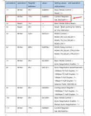
    Below is my configuration sequence for the PHY initialization register. Is it necessary to add the second step? Or is there any benefit in adding it?

    3、What is the difference between SW_RESET and SW_RESTART?

    I may need to ask you some more questions in the future, and it won't take too long. I won't close this topic for now.Thank you so much.

  • Hi Sheng,

    1) Register 0x1[2] is initialized as '0' on power-up before link. When link is up, this value may not update until the past value is cleared on register read:

    For state machine logic to check link up, I recommend reading the 0x1[2] two times to confirm accurate link status.

    2) While this step is not always required, it's recommended to restart the PHY's internal state machine for a "fresh" configuration to attempt link-up.

    3) Both SW_RESET and SW_RESTART will restart the PHY's internal state machine. However, only SW_RESET will refresh the registers to their default values.

    Thank you,

    Evan

  • HI.Mayhew

    Thanks for your reply.

    The second part of the reply.I don't understand.

    2) While this step is not always required, it's recommended to restart the PHY's internal state machine for a "fresh" configuration to attempt link-up.

    I added the SW_RESTART operation in the hope that the PHY initialization process will not be affected by an external reset, causing the configuration register to fail.Is it necessary for me to add this step?Or what are the benefits of adding this step?I've read other people's suggestions, but I'm not sure if I need to add this step.

  • Hi Sheng,

    Yes, the first two steps are recommended.

    0x0[15] = '1' will perform a full restart of the PHY and reset the registers to default/strap values.

    0x1F = 0x4000 will restart the internal state machine of the PHY.

    The goal of both of these steps is to prepare the PHY for configuration, by restarting it to the default state for both straps and internal state machine.

    Without this step, there are possible edge cases where the PHY may get stuck in unknown / unconfigurable state until reset.

    0x1F = 0x4000 is also recommended again as the last step of configuration, so the PHY's internal state machine can restart and begin link with the set configuration.

    Please let me know if this is clear.

    Thank you,

    Evan