This thread has been locked.

If you have a related question, please click the "Ask a related question" button in the top right corner. The newly created question will be automatically linked to this question.

TUSB1002A: Questions about datasheet

Part Number: TUSB1002A
Other Parts Discussed in Thread: TUSB216,

Tool/software:

Hi team,

I have some questions about datasheet. 

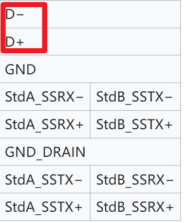
(1) USB3.0 should also have D+ and D- pins. Why TUSB1002A only have 2 channels? Does customer need to add an additonal TUSB216 to compensate the D+ and D-? 
(2) What's LOS and LFPS and Rx detect? 
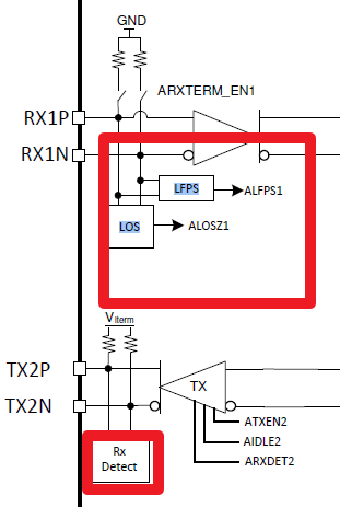
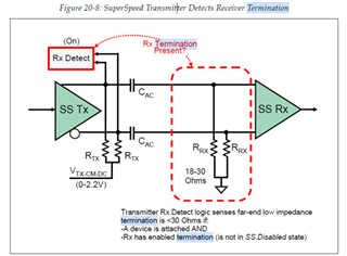
(3) Couldy you please illustrate the far-end receiver termination? I think the connection detection should happen at RX pins. 

(4) What's electrical idle? Does it mean we disconnect the slave device from USB interface? 

(5) Why the AC cap is 220nF for CH1 but 330pF or DC-coupled for CH2?

(6)How to understand below word? 

  • Hi Nison,

    1. D+ and D- are USB2, not USB3. You are correct that the customer needs a USB2 re-driver to compensate those signals.

    2. LOS is a flag that detects when a valid signal is being transmitted to the receiver (RX) on the 1002A. LFPS is the low-frequency periodic signaling detection in our device that passes LFPS during the USB3 handshake process between a connected host and device. RX detect is a pulse sent out by the transmitters (TX) on the 1002A to look for a connected host and device.

    3. The RX pins have terminations on them (Rrx) that need to be detected by the connected transmitter so a connection can be established. The transmitter is where the detection happens, not the receiver.

    The transmitter (TX) will send out a pulse that looks for terminations on the RX lines. Once these terminations are detected, the host/device will transition to LFPS.

    4. Electrical idle is when there is no activity on the interface (no data transmitted). This is not the same as disconnect because the host/device is still connected, with terminations on RX present. When the interface is idle for long enough, we transition to a low power mode U1 --> U2/U3.

    5. All USB3 transmitters need to be AC coupled with 220nF, the receiver (RX) connected to the USB connector can be optionally AC coupled with 330nF to keep total capacitance within the USB spec. The capacitor is not required on the RX to the connector because the connected transmitter will have a capacitor that falls within the USB spec (75 - 265nF).

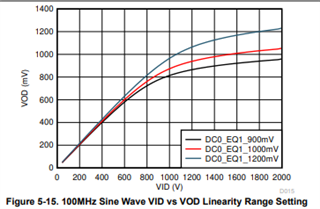
    6. Vid is the input swing amplitude of your signal. The 1002A will take in the signal with Vid amplitude and output the signal with Vod amplitude.

    If Vid is too low, then Vod will also decrease which lowers the amplitude of the output signal. You can use DC gain to 'boost' the output signal if this is the case.

    Best,

    Shane

  • Hi Shane -

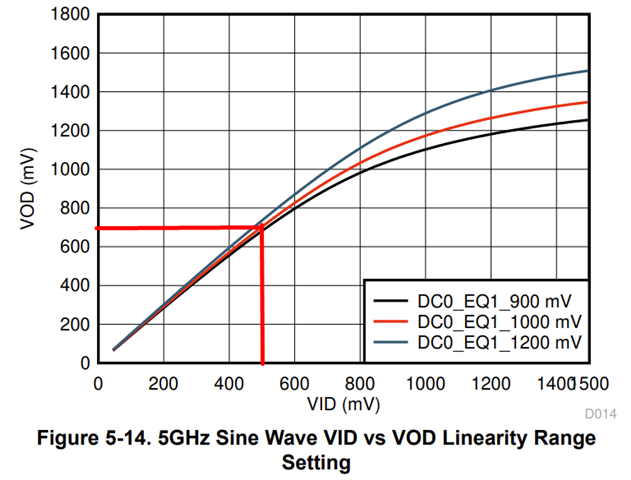
    Thank you for this information that you shared above. It's very helpful. For question 6, what is the minimum  "USB 3.2 defined swing" on Vod?  In my application, the controller that driving the RX of the TUSB1002A provides a differential output voltage ~0.5V. We only utilize 5Gbps USB 3.1 data.

    If I'm understanding this graph correctly, then when transmitting USB3.1 data at 5Gbps with a Vid = 0.5V we should see a differential output voltage around 0.7V: 

    Is that going to be within the appropriate USB3.1 defined swing range?

    -Shane Kent

  • Hi Shane,

    The USB compliance test for differential output voltage allows a range from 100mV to 1.2V at 5Gbps. 0.7V would be ok for the output swing.

    Often when you are operating at high speeds like 5 - 10Gbps, the signal amplitude will not reach the full output swing set by the USB host. This is why the lower limit in the compliance test is a relatively low 100mV.

    Best,

    Shane (Hauser)

  • Great! Thanks for the info! 

    -Shane