Tool/software:
Most redrivers and retimers advertise their equalization capabilities in dB but its difficult to quantify what that represents in terms of cable length. This FAQ is a guide to determine how long of a cable can be supported by a signal conditioner.
- Determine if the cable will be connected on the receiver end or transmitter end of the signal conditioner
- When using a signal conditioner where the cable will be connected to the receiver end, the biggest care about is the receiver equalization (RX EQ). This value is a key attribute of any signal conditioner and will be available on the signal conditioner datasheet, keep in mind this RX EQ value will be at a defined frequency or datarate. The relationship is 2x frequency = datarate Locate and note this RX EQ value and the frequency.
- The cable you are planning to use for cable reach testing must be a cable that has passed compliance and is within tolerances of the defined protocol specification
- For example, an HDMI cable is defined in the HDMI specification under section 5, and the electrical specification can be found under section 5.1.1.1
- A cable vendor must pass testing to prove its parameters are within the defined specification.
- The cable vendor will have information regarding the loss of the cable at a defined frequency of signaling. Ideally, they have a bode plot defining the loss of a cable across a variety of frequencies.
- Here is an example of a cable loss plot:
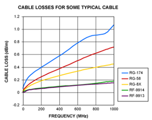
- Increasing the frequency of signaling will always result in more loss. Because of this relationship always test max cable reach at the maximum data rate intended for use. Continuing with the HDMI example, the maximum datarate for HDMI2.1 is 12Gbps. This means the signal frequency of interest is 6GHz.
- After gathering the loss profile of the cable and the RX EQ capability of the signal conditioner, you are ready to determine the maximum cable length with that vendor. This becomes a simple division problem
- [RX EQ (dB)/ Loss profile (dB/m) = total length (m)]
- The cable you are planning to use for cable reach testing must be a cable that has passed compliance and is within tolerances of the defined protocol specification
- When looking at a signal conditioner where the cable will be connected on the TX end, the process becomes a little more abstract. This is because we will not know the receiver equalization capability.
- The first step is to verify that the cable used follows the electrical characteristics defined in the protocol specification.
- The next step is to run protocol compliance with the maximum TX driver settings
- This includes but is not limited to, slew rate, voltage swing, pre-emphasis, and de-emphasis.
- When running compliance make sure that there is no cable model being applied on top of the existing physical cable used for compliance. For example, in HDMI compliance testing there is a short-cable model eye diagram and a long-cable model eye diagram.
- In the short-cable model there is a small loss profile added onto the exiting physical cable so results will be marginally worse than expected.
- However, the long cable model adds the loss profile of the worst possible cable that is defined in the HDMI spec. This loss profile will be added on top of the physical cable being tested. This most likely will fail the eye diagram test, but is not cause for concern as this test is a moot point.
- Determine the maximum physical cable length that can be used by using the longest cable tested with a passing compliance report. This can also be verified functionally by plugging in the TX to a data sink.